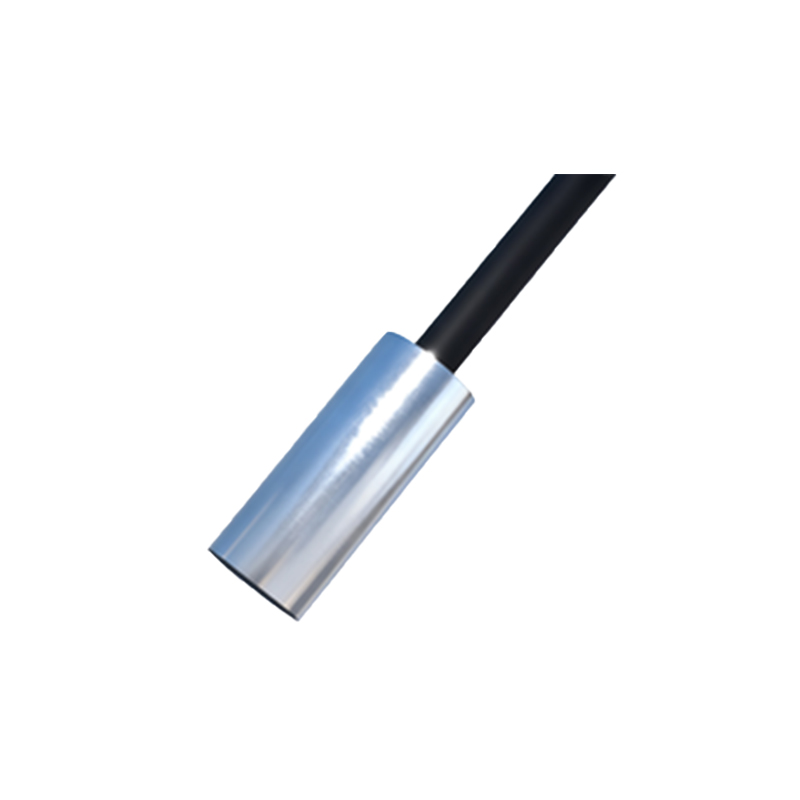
Proximity sensors are essential components in modern industrial automation, widely used for object detection, positioning, and control without physical contact. Proper wiring is critical to ensure reliable operation, safety, and longevity of these sensors. This guide provides a step-by-step approach to wiring proximity sensors, covering common types, connection methods, and best practices.
First, identify the type of proximity sensor you are working with. The two main categories are inductive and capacitive sensors, each suited for different materials and environments. Inductive sensors detect metallic objects, while capacitive sensors can sense both metallic and non-metallic materials. Additionally, sensors come in various output configurations: NPN (sinking) and PNP (sourcing), as well as normally open (NO) or normally closed (NC) contacts. Check the sensor’s datasheet or label to confirm its specifications, including voltage rating (typically 10-30V DC or 20-250V AC), output current, and wiring diagram.
Before starting, ensure all power sources are disconnected to prevent electrical hazards. Gather necessary tools, such as wire strippers, screwdrivers, and a multimeter for testing. Most proximity sensors have three or four wires: brown (positive), blue (negative), black (output), and sometimes white (complementary output or diagnostic). For DC sensors, connect the brown wire to the positive terminal of the power supply and the blue wire to the negative terminal. The black wire is the output signal, which should be connected to the load (e.g., PLC input, relay, or indicator). In PNP sensors, the output provides positive voltage when activated, while NPN sensors sink current to ground.
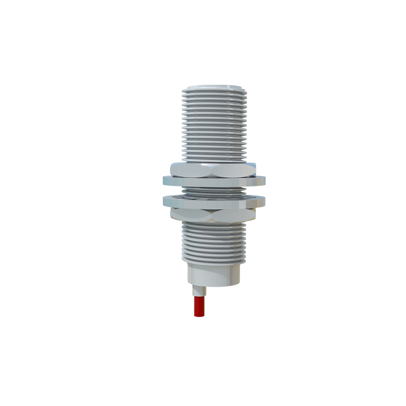
For AC sensors, wiring differs slightly. Typically, brown is live (L+), blue is neutral (N), and black is the output. Ensure the power supply matches the sensor’s voltage and frequency (e.g., 120V AC, 50/60Hz). Use shielded cables in environments with high electromagnetic interference (EMI) to prevent false triggering. Ground the shield at one end only, preferably at the control panel, to avoid ground loops.
When connecting to a programmable logic controller (PLC), match the sensor’s output type with the PLC input module. PNP sensors work with sinking PLC inputs, while NPN sensors require sourcing inputs. Verify polarity carefully; incorrect connections can damage the sensor or PLC. For redundant systems, use sensors with dual outputs (e.g., NO and NC) for fail-safe applications.
Testing is crucial after wiring. Reconnect power and observe the sensor’s indicator LED. When a target object enters the sensing range, the LED should illuminate, and the output signal should change state. Use a multimeter to measure voltage at the output wire: for PNP, it should read near supply voltage when active; for NPN, it should drop to near zero. Adjust the sensor’s sensitivity or positioning if detection is inconsistent.
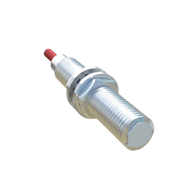
Maintenance tips include regular inspection for wear, corrosion, or loose connections. Keep sensors clean from dust, oil, or metal shavings, as contaminants can affect performance. Follow manufacturer guidelines for environmental ratings (IP67 for waterproofing, high-temperature resistance) to ensure durability in harsh conditions.
In summary, correct wiring of proximity sensors involves understanding sensor types, adhering to color codes, matching outputs with control devices, and thorough testing. By following these steps, engineers can optimize system reliability and minimize downtime in industrial applications.