In precision engineering and manufacturing, the accurate alignment of laser systems is paramount. A misaligned laser head can lead to significant errors in cutting, engraving, welding, or measurement applications. The laser head tilt sensor is a critical component that monitors and helps correct angular deviations. Proper adjustment of this sensor ensures optimal system performance, repeatability, and longevity. This guide provides a detailed, step-by-step procedure for engineers to correctly adjust a laser head tilt sensor, adhering to industry best practices.
Before initiating any adjustment, comprehensive preparation is essential. First, consult the specific manufacturer's manual for your laser system and sensor model. Specifications and procedures can vary significantly between brands like Coherent, IPG Photonics, or TRUMPF. Ensure the laser system is completely powered down and locked out following standard safety protocols (LOTO). Gather the necessary tools: typically, precision hex wrenches, a high-quality spirit level or digital inclinometer, calibration targets, and a computer with the system's control software installed. The work environment should be stable, free from vibrations, and at a consistent temperature to prevent thermal expansion from affecting measurements.
The core adjustment process begins with establishing a reliable reference plane. Use a precision machined surface or the machine's own validated datum as your reference. Place a high-accuracy spirit level or digital inclinometer on this reference surface and zero the instrument. This establishes your baseline for "level." Next, carefully mount the laser head tilt sensor onto its bracket or housing, ensuring it is mechanically secure but not overtightened, as this can induce stress and cause reading errors.
Power on the control system and software, but ensure the laser emission itself is disabled for safety. Navigate to the sensor calibration or alignment menu within the software interface. Most modern systems provide real-time feedback from the tilt sensor, displaying angular values in two axes (often labeled as X-tilt and Y-tilt, or Pitch and Roll). Observe the initial readings. They will likely show a deviation from zero, indicating the current tilt.
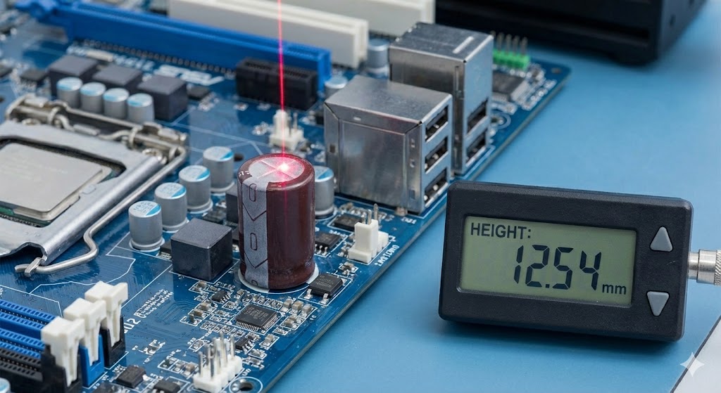
The physical adjustment is performed using the set screws or micro-adjustment knobs on the sensor mount or the laser head assembly itself. Make minute, incremental adjustments—often a quarter-turn or less at a time. The golden rule is: adjust one axis at a time. For instance, first address the X-axis (Pitch). Make a small adjustment, then observe the feedback on the software readout. Allow the system a moment to stabilize, as some sensors have a brief data averaging period. Continue this process until the reading for that axis is as close to zero as possible.
Once the first axis is nulled, proceed to the second axis (Y-axis or Roll). Repeat the meticulous process of tiny adjustments and observation. It is crucial to understand that adjusting the second axis can slightly affect the first due to mechanical coupling. Therefore, after initially setting both axes, you must iterate the process. Go back to the first axis, check its reading, make a fine correction if needed, then re-check the second axis. Several iterations may be necessary to achieve a stable null reading (e.g., within ±0.005 degrees or as per your system's specification) on both axes simultaneously.
After achieving a satisfactory software null, a physical verification is mandatory. With the laser power still off, use your calibrated spirit level or digital inclinometer placed directly on a verified flat surface of the laser head assembly. Compare this physical measurement with the sensor's software reading. They should correlate closely. Any significant discrepancy may indicate an issue with the sensor's mounting, the reference surface, or the sensor itself.
For systems involved in high-precision tasks, a functional test is the final step. Using a safe, low-power setting or a visible alignment laser, direct the beam onto a calibrated target or perform a test run on a non-critical material. Analyze the result for uniformity and edge quality. Consistent errors across the workpiece may indicate a residual tilt that needs further fine-tuning.
Common pitfalls during adjustment include rushing the process, making overly large adjustments, neglecting thermal stabilization of the system, and forgetting to re-tighten locking screws after final adjustment (if applicable). Always follow a torque specification if provided. Furthermore, environmental factors like floor stiffness, air currents, and nearby equipment can introduce drift; continuous monitoring over a short period after adjustment is advised.
Regular maintenance of the tilt sensor and its mounting hardware is also key to sustained accuracy. Schedule periodic checks according to the machine's maintenance calendar or based on usage hours. Document every adjustment procedure, noting initial readings, adjustments made, final readings, and the date. This log is invaluable for troubleshooting future drift issues and for predictive maintenance.
In summary, adjusting a laser head tilt sensor is a methodical process that blends mechanical precision with digital feedback analysis. By meticulously preparing, adjusting one axis at a time, iterating for coupling effects, and always verifying with physical measurements, engineers can ensure their laser systems operate at peak accuracy and reliability, minimizing waste and maximizing productivity in demanding industrial applications.