Understanding how to properly wire a laser sensor is fundamental for ensuring accurate measurements, reliable operation, and system safety in industrial automation, robotics, and various sensing applications. This guide provides a clear, step-by-step walkthrough of common wiring configurations, supported by explanatory diagrams to help both beginners and experienced technicians.
A laser sensor typically has three main functional components: the power supply terminals, the output signal terminals, and often a control or teaching input. The most common types of outputs are NPN (sinking) and PNP (sourcing) digital signals, though analog (4-20 mA or 0-10 V) and relay outputs are also available. The wiring process always begins with consulting the specific sensor's datasheet, as pin assignments, voltage requirements, and colors can vary between manufacturers and models.
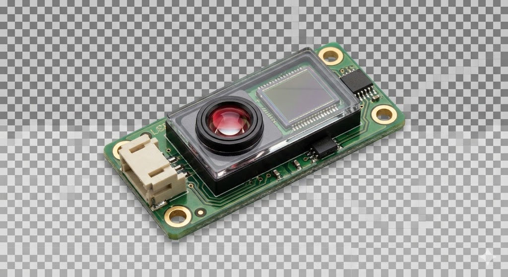
Standard Wiring Components and Safety
Before starting, ensure you have the correct tools: appropriate wire strippers, screwdrivers, and possibly a multimeter. Always disconnect power before making any connections. You will typically need a DC power supply. Common voltages are 12-24 VDC. The basic wires you will connect are:
* Brown (or Red): This is the positive voltage supply wire (+V).
* Blue (or Black): This is the negative voltage supply wire (0V or GND).
* Black (or White): This is the output signal wire. The state of this wire (high or low voltage) changes when the sensor detects an object.
* Other colors (e.g., White, Gray): Often used for control inputs like a teach-in function or for a second complementary output.
Wiring a PNP (Sourcing) Sensor
A PNP sensor *sources* current to the load. When activated, it connects the load to the positive supply voltage.
1. Connect the Brown wire to the positive terminal (+) of your DC power supply (e.g., +24V).
2. Connect the Blue wire to the negative terminal (-) or 0V (ground) of the power supply.
3. Connect the Black output wire to one terminal of your load (e.g., a PLC input, relay coil, or indicator light).
4. Connect the other terminal of your load back to the power supply's 0V (ground).
In this configuration, when the sensor detects an object, the Black wire will supply +24V to the load, completing the circuit to ground and activating it.
Wiring an NPN (Sinking) Sensor
An NPN sensor *sinks* current from the load. When activated, it connects the load to ground (0V).
1. Connect the Brown wire to the positive terminal (+) of your DC power supply.
2. Connect the Blue wire to the negative terminal (0V/ground) of the power supply.
3. Connect one terminal of your load to the positive supply voltage (+V).
4. Connect the other terminal of your load to the Black output wire of the sensor.
Here, when the sensor activates, the Black wire provides a path to ground (0V), allowing current to flow from the supply, through the load, and into the sensor to ground, thus activating the load.
Wiring Diagrams and Practical Considerations
Accompanying diagrams are essential for visualization. A simple diagram would show the power supply, the sensor block with labeled terminals (V+, V-, Out), and the load, with clear lines indicating wire connections for both PNP and NPN setups. For analog sensors, the wiring is similar, but the output wire carries a varying current or voltage proportional to the measured distance or presence.
Key Steps for Successful Wiring:
1. Identify Your Sensor Type: Check the label or datasheet for "PNP" or "NPN," and note the operating voltage range.
2. Identify Your Load: Determine if your PLC, controller, or relay module is configured to accept a PNP (sourcing) or NPN (sinking) signal. Mismatching can lead to non-operation or damage.
3. Plan the Circuit: Sketch the connection, including the power source, sensor, and load, before making physical connections.
4. Make Secure Connections: Ensure wire terminations are tight and insulated to prevent short circuits or loose connections that cause intermittent faults.
5. Test Systematically: After wiring, apply power. Use the sensor's indicator LED and a multimeter to verify the output signal changes state correctly when an object is presented to the laser beam.
Troubleshooting Common Issues
* No Power/No LED: Verify power supply voltage and polarity. Check fuse.
* Sensor On Constantly: Check for wiring errors, especially load connection. Ensure the sensing object is outside the calibrated range.
* Intermittent Operation: Check for loose wires, poor connections, or electrical noise. Ensure wires are not run parallel to high-voltage AC lines.
* Incorrect Signal: Confirm PNP/NPN compatibility between sensor and load. Verify with a multimeter if the output switches between near-supply-voltage and near-zero-voltage correctly.
Proper wiring forms the foundation of any laser sensor installation. By following these principles, referring to the manufacturer's documentation, and using clear diagrams as a reference, you can ensure a robust and functional setup that delivers precise and dependable performance for your application.