In the high-precision world of industrial fabrication, laser cutters are indispensable tools. Their efficiency and accuracy, however, are heavily reliant on a network of sophisticated sensors. These components act as the machine's sensory organs, monitoring everything from beam alignment and gas pressure to temperature and positional feedback. When a sensor malfunctions or reports an error, it can lead to catastrophic results: ruined workpieces, damaged optics, costly downtime, and significant safety hazards. For engineers and maintenance technicians, a systematic approach to diagnosing and resolving these errors is paramount. This article delves into the common types of laser cutter sensor errors, their root causes, and proven troubleshooting methodologies.
The first category of common errors revolves around Beam Path and Alignment Sensors. Modern laser cutters often incorporate beam diagnostic sensors, such as CCD cameras or photodiodes, to monitor the laser's position, focus, and mode. An error here typically manifests as poor cut quality—uneven edges, excessive dross, or failure to pierce material. The root cause can be a misaligned sensor itself, contamination on its lens from smoke or debris, or a failure in the signal processing unit. Troubleshooting begins with a visual inspection and cleaning of the sensor's optical surface. Subsequently, running the machine's automated beam alignment routine is essential. If errors persist, calibrating the sensor's offset values or checking the integrity of its cabling for electromagnetic interference (EMI) is the next step. A failing sensor will often provide erratic or out-of-range feedback signals, identifiable with a multimeter or oscilloscope.
Gas Pressure and Flow Sensors are critical for processes like oxygen-assisted cutting or nitrogen cutting for stainless steel. Errors from these sensors usually trigger immediate machine stops or prevent the laser from firing. A "Low Assist Gas Pressure" alarm is frequent. The fault tree is extensive: it could be an actual issue with the external gas supply (empty cylinder, clogged regulator), a leaking solenoid valve, a blocked nozzle, or the pressure transducer itself. The sensor's diaphragm can fail, or its electrical connection can corrode. Diagnosis involves a step-by-step isolation process. First, verify the supply pressure at the source. Then, use the machine's manual control to activate the gas solenoid and check pressure at the cutter head, bypassing the machine's internal monitoring if safe and possible. Comparing the sensor's readout on the CNC controller with a trusted external gauge is a direct way to confirm sensor accuracy.
Temperature Monitoring Sensors, including thermocouples and RTDs (Resistance Temperature Detectors), protect the laser resonator, optics, and motion system. Over-temperature errors can shut down the laser generator or the entire machine. Common culprits are inadequate cooling—caused by low coolant levels, a failing pump, clogged filters, or a dirty heat exchanger. However, the sensor itself can be at fault. A thermocouple may become decalibrated or suffer from a broken junction, leading to false high or low readings. Troubleshooting requires checking the actual temperature at the component (using a non-contact infrared thermometer for comparison) and verifying the cooling system's performance (flow rate, coolant temperature). Electrical testing of the sensor for proper resistance or millivolt output is often necessary.
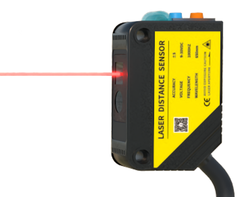
Positional Feedback Sensors, primarily encoders (linear and rotary) and limit switches, ensure the cutting head moves accurately along its programmed path. Errors here result in positional inaccuracies, contour deviations, or "axis drive fault" alarms. Linear scale encoders can be contaminated by metallic dust or coolant, causing read head failures. Rotary encoders on servo motors can have their internal glass discs cracked. Limit switches may become mechanically misaligned or fail electronically. Diagnostic procedures often involve the machine's diagnostic page, observing the feedback values while manually jogging the axis. Erratic jumps in position data point to encoder issues. Physically cleaning encoder scales with approved solvents and checking for secure mounting are standard first responses. For networked encoders, checking the integrity of the communication protocol (e.g., EnDat, BiSS) is also crucial.
A systematic troubleshooting protocol is vital. Always start by consulting the machine's error log and manual for specific fault codes. Safety First: Ensure the machine is fully powered down and locked out (LOTO) before any physical inspection, especially for high-voltage laser power supplies. The initial step is often a visual and auditory inspection for obvious signs like loose connectors, damaged wires, or burnt components. Use diagnostic tools: a multimeter for continuity and voltage checks, an oscilloscope for signal integrity, and a pressure gauge for pneumatic/hydraulic systems. Do not overlook software; sometimes, a corrupted parameter file or a bug in the CNC software can cause persistent false sensor alarms. After any repair or sensor replacement, comprehensive recalibration and a test run on scrap material are mandatory before resuming production.
Preventive maintenance is the most effective strategy against sensor errors. Implement a regular schedule that includes cleaning optical sensors and encoder scales, checking and tightening all electrical connections, verifying gas system integrity, and ensuring cooling system efficiency. Keeping a log of all sensor-related incidents helps identify recurring issues or sensors nearing their end of life. By understanding the critical role of each sensor and adopting a disciplined, analytical approach to faults, engineers can minimize unplanned downtime and maintain the laser cutter at its peak operational performance, ensuring both quality and safety in the workshop.