In the realm of industrial automation and control systems, proximity sensor switches stand as fundamental components for non-contact object detection. Moving beyond basic operational principles, intermediate-level applications demand a deeper understanding of sensor encoding—the critical process of configuring and interpreting the sensor's output signal to interface seamlessly with Programmable Logic Controllers (PLCs), counters, and data acquisition systems. This guide delves into the core aspects of proximity switch encoding, focusing on output types, wiring schemes, and practical implementation strategies.
The primary division in proximity sensor encoding lies in its output configuration. The two predominant types are Digital (Discrete) and Analog outputs. Digital output sensors, the most common in switch-like applications, provide a simple ON/OFF signal. This binary operation is further categorized into two sinking (NPN) and sourcing (PNP) transistor outputs. A PNP sensor switches the positive voltage line to the load, while an NPN sensor switches the negative or ground line. Misunderstanding this distinction is a frequent source of wiring errors and PLC input incompatibility. The encoding here is straightforward: a high logic level (e.g., +24V DC) typically indicates target presence, while a low logic level (0V) indicates absence, or vice-versa depending on the logic (normally open/closed) configuration.
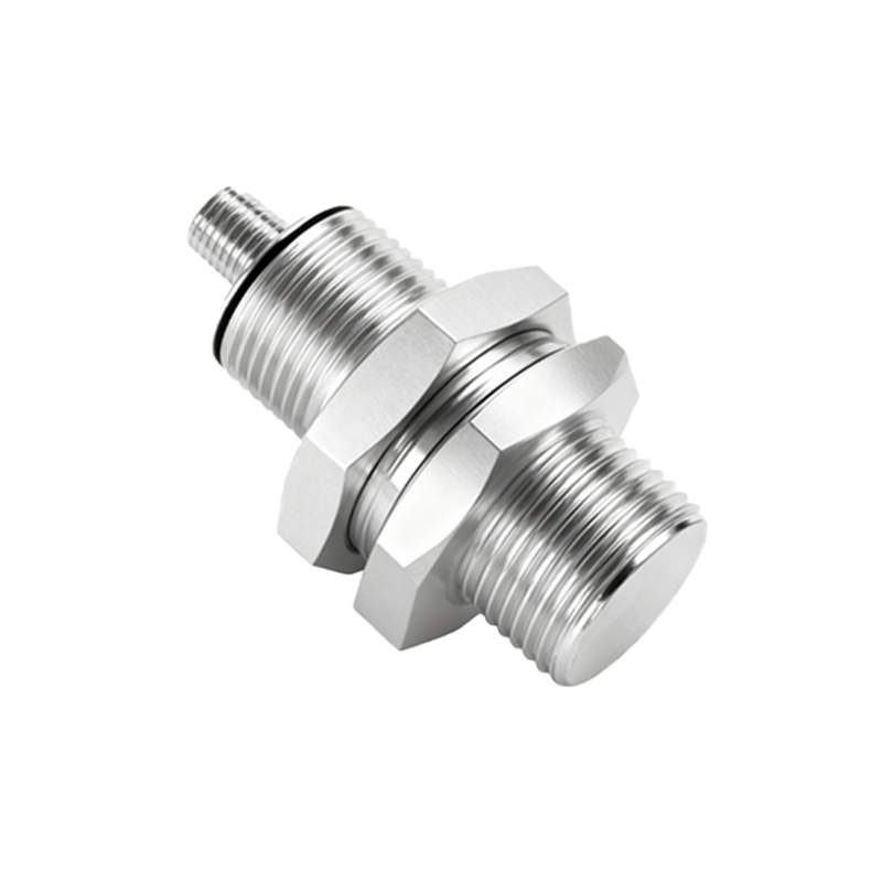
Analog output sensors, such as those with 4-20 mA or 0-10 V DC outputs, encode information proportionally. Instead of mere presence, they convey data on distance or other measured parameters. For instance, an inductive analog proximity sensor might output 4 mA when a target is at its maximum sensing distance and 20 mA when the target is at the minimum. The encoding challenge shifts from wiring to scaling—calibrating the PLC or receiver to correctly interpret the current or voltage range into meaningful engineering units (e.g., millimeters).
Wiring and interface encoding are paramount for system integrity. A standard 3-wire DC sensor comprises power (brown/+), ground (blue/-), and output (black) wires. The encoding of the output wire's behavior is defined by the sensor's datasheet. For connection to a PLC digital input module, one must ensure compatibility: a PNP sensor's sourcing output should connect to a sinking PLC input, and an NPN sensor's sinking output to a sourcing PLC input. Modern sensors often feature programmable outputs or IO-Link communication. IO-Link represents a significant leap in encoding sophistication. It is a point-to-point serial communication protocol that allows for bidirectional data exchange. Beyond the simple switch signal, an IO-Link sensor can transmit detailed parameter data (e.g., operating hours, temperature, calibration values) and receive configuration commands from the master. This transforms the sensor from a simple switch into an intelligent, encoded data point on the network.
Noise immunity and timing parameters are subtle yet crucial encoding considerations. Sensors in electrically noisy environments may require shielded cables, with the shield properly grounded at one end to prevent ground loops. Timing parameters like response time, switch-on/switch-off delay, and operating frequency must be encoded into the control logic. For high-speed counting or precise positioning applications, a sensor with a 1 ms response time encodes event timing far more accurately than one with a 10 ms response. Furthermore, some sensors offer teach-in functionality, allowing for on-site encoding of the sensing distance or output delay via a push-button or magnetic tool, providing flexibility for changing application requirements.
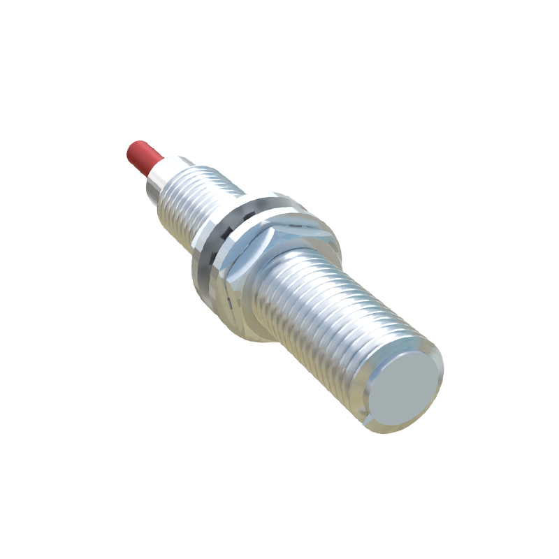
In practice, successful encoding involves a systematic approach. First, meticulously review the sensor datasheet for its electrical characteristics, output type, and pinout. Second, design the interface circuit, ensuring correct power supply ratings and load compatibility (including protection diodes for inductive loads). Third, program the PLC or controller to decode the incoming signal correctly. This includes setting the correct input card type, defining alarm thresholds for analog signals, and implementing software debouncing filters for digital signals if necessary. Finally, thorough testing under real-world conditions validates the encoding scheme. Use a multimeter to verify voltage/current levels and oscilloscopes to inspect signal integrity in dynamic scenarios.
Mastering intermediate proximity sensor encoding empowers engineers to select the optimal sensor, design robust interfaces, and troubleshoot complex systems efficiently. It bridges the gap between the physical detection event and the digital control logic, ensuring reliable, accurate, and maintainable automation solutions. As sensors evolve towards greater intelligence and connectivity, the principles of clear signal definition, proper interfacing, and precise interpretation remain the bedrock of effective system encoding.