Proximity sensors are critical components in industrial automation, manufacturing lines, and safety systems, detecting the presence or absence of objects without physical contact. When these sensors malfunction, they can lead to production downtime, safety hazards, or inaccurate data. As an experienced electrical engineer, I will guide you through systematic steps to diagnose and repair common proximity sensor issues, ensuring reliable operation and minimal disruption.
First, understand the type of proximity sensor you are dealing with—inductive, capacitive, or photoelectric—as each has unique characteristics and failure modes. Inductive sensors detect metallic objects, capacitive sensors sense both metallic and non-metallic materials, and photoelectric sensors use light beams. Knowing the sensor type helps narrow down potential problems.
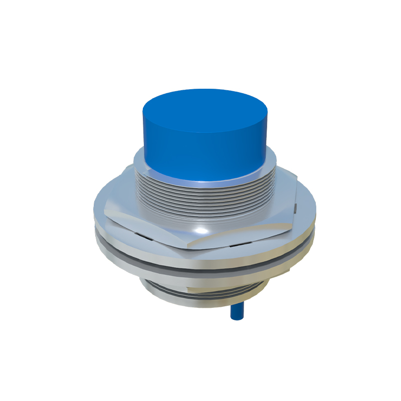
Start with a visual inspection. Check for physical damage, such as cracks, corrosion, or loose connections. Ensure the sensor is properly mounted and aligned, as misalignment can cause false readings. Look for environmental factors like dust, moisture, or temperature extremes that might affect performance. Clean the sensor lens or surface with a soft cloth and appropriate cleaner, avoiding abrasive materials that could scratch sensitive parts.
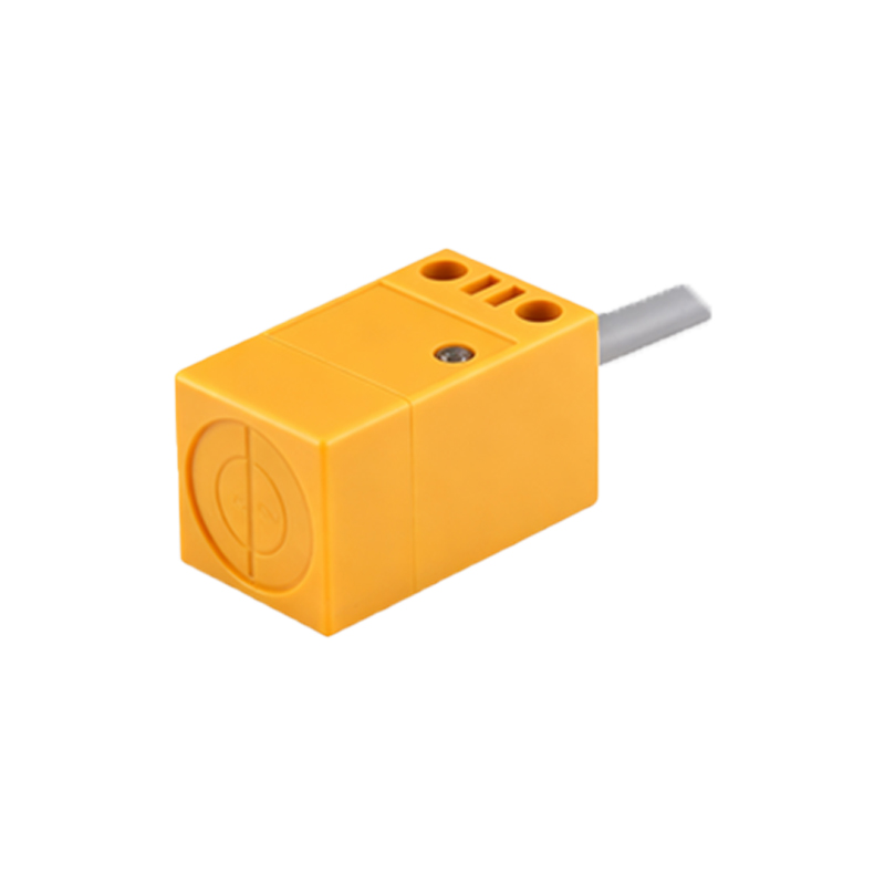
Next, verify the power supply. Use a multimeter to measure the voltage at the sensor terminals, comparing it to the manufacturer’s specifications (typically 10-30V DC for most models). Fluctuations or low voltage can indicate power supply issues, faulty wiring, or overloaded circuits. Ensure the grounding is secure, as poor grounding often leads to erratic behavior. If the power supply is unstable, consider adding a stabilizer or checking the circuit for shorts and breaks.
Test the sensor output. Connect the multimeter or an oscilloscope to the output terminals to monitor the signal. For a normally open (NO) sensor, the output should switch from low to high when an object is within the sensing range. If there is no change, the sensor might be defective or incorrectly configured. Adjust the sensing distance if applicable, as wear over time can reduce sensitivity. For programmable sensors, review the settings via the interface to ensure parameters like hysteresis or response time are correctly set.
Inspect the load and wiring. A common issue is overloading the sensor with excessive current, which can damage internal components. Check the load rating and ensure it matches the connected device (e.g., PLC input, relay). Examine wiring for frayed insulation, loose terminals, or crossed wires. Use continuity tests to identify breaks in the circuit. For shielded cables, verify that the shielding is properly grounded to prevent electromagnetic interference (EMI), which can cause false triggers.
If basic checks do not resolve the problem, delve into component-level troubleshooting. For inductive sensors, the oscillator coil may degrade, leading to reduced sensing range. Capacitive sensors might suffer from dielectric changes due to contamination. Photoelectric sensors could have LED or phototransistor failures. In such cases, refer to the sensor’s datasheet for test points and expected values. Replace faulty components if possible, but note that many modern sensors are sealed units, requiring complete replacement for cost-effectiveness.
Consider environmental interferences. Proximity sensors can be affected by nearby machinery, high-frequency noise, or other sensors operating on similar frequencies. Relocate the sensor or install ferrite cores on cables to mitigate EMI. For high-vibration areas, ensure mounting hardware is tight and use vibration-resistant models. In corrosive environments, select sensors with appropriate IP ratings (e.g., IP67 for dust and water resistance).
When repairs are not feasible, replacement is the best option. Choose a sensor with matching specifications—voltage, output type (PNP/NPN), sensing range, and housing material. Document the failure cause to prevent recurrence, such as implementing regular maintenance schedules or upgrading to more robust models. Always follow lockout-tagout (LOTO) procedures during repair to ensure safety.
In summary, troubleshooting proximity sensors involves a methodical approach: identify the sensor type, inspect physically, test electrical parameters, and address environmental factors. Regular maintenance, including calibration and cleaning, can extend sensor life and prevent unexpected failures. By mastering these techniques, engineers can minimize downtime and maintain efficient, safe operations in industrial settings.