In the intricate world of industrial automation and machinery control, the reliable detection of rotational position, speed, and direction is paramount. Among the suite of sensors enabling this functionality, rotary proximity switch sensors stand out for their robustness, non-contact operation, and versatility. This article delves into the operational principles, key types, application considerations, and selection criteria for these critical components in modern electromechanical systems.
At its core, a rotary proximity switch sensor is a non-contact device designed to detect the presence, absence, or position of a metallic target attached to a rotating shaft. Unlike mechanical limit switches that require physical contact, these sensors operate on electromagnetic principles, primarily inductive sensing. A typical inductive rotary proximity sensor consists of an oscillator circuit that generates a high-frequency electromagnetic field at its active face. When a ferrous metal target (such as a gear tooth, cam lobe, or dedicated flag) passes through this field, eddy currents are induced in the target. This causes a measurable change in the oscillator's amplitude or frequency. An integrated evaluation circuit detects this change and triggers a solid-state switching output, typically in the form of a PNP, NPN, or relay contact signal.
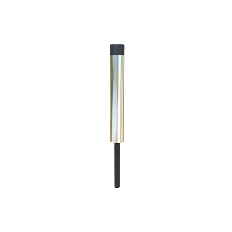
Several key configurations define the landscape of rotary proximity sensors. The most common is the rotary cam proximity switch, where one or more adjustable metallic cams are mounted on a shaft. As the shaft rotates, the cams pass by a stationary sensor head, generating discrete on/off signals used for sequential control, such as initiating specific machine cycles at precise angular positions. Another vital type is the gear tooth sensor or rotary speed sensor. Here, a standard gear or a dedicated pulse wheel serves as the target. Each tooth passing the sensor generates a pulse, allowing for precise measurement of rotational speed (RPM) and, with multiple sensors, direction. For applications requiring absolute position feedback, rotary encoder-style proximity systems utilize a coded disk with a unique pattern of metallic and non-metallic sections, read by an array of sensors to determine the exact shaft angle.
The advantages of using rotary proximity switches are significant. Their non-contact nature eliminates mechanical wear, leading to exceptionally long service life and reduced maintenance. They are immune to dust, oil, vibration, and other harsh environmental factors common in industrial settings, provided they have appropriate ingress protection (IP) ratings. They offer high switching frequencies, enabling detection at very high rotational speeds. Furthermore, they provide precise and repeatable detection, which is crucial for process quality and machine safety.
Applications for these sensors are vast and cross-industrial. In material handling, they monitor conveyor drive speeds and detect jams. In packaging machinery, they ensure precise cutting and filling positions. Automotive assembly lines use them for robotic arm positioning and part presence verification. In metalworking, they control the indexing of turrets and spindles. They are also fundamental in wind turbines for monitoring blade pitch and yaw position, and in agricultural equipment for controlling seed metering and implement position.
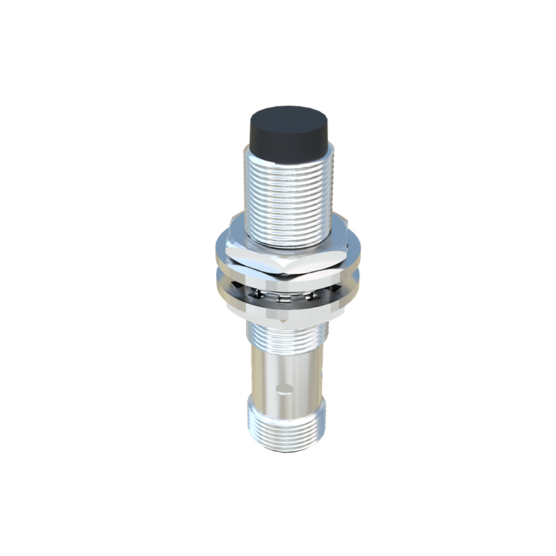
Selecting the right rotary proximity switch requires careful consideration of several parameters. First, define the sensing object: the material (steel, stainless steel, aluminum), size, and shape of the target. Ferrous metals provide the best sensing range. The operating distance or switching distance must be specified, ensuring a sufficient gap between the sensor and target to account for mechanical tolerances and thermal expansion. Output type is critical: PNP (sourcing) or NPN (sinking) transistor outputs are standard for PLC integration, while some applications may require analog (4-20mA, 0-10V) or IO-Link digital communication outputs for advanced diagnostics and parameterization. Environmental conditions dictate the required housing material (often nickel-plated brass or stainless steel), IP rating (e.g., IP67 for washdown environments), and temperature range. For speed sensing, the maximum switching frequency must exceed the maximum pulse frequency generated by the target. Finally, mechanical factors like shaft size, mounting style (bracket or threaded barrel), and connection type (pre-wired cable or quick-disconnect) must align with the machine design.
Installation and alignment are crucial for optimal performance. The sensor must be mounted securely to prevent vibration-induced errors. The air gap should be set according to the datasheet, typically 50-80% of the nominal sensing distance to account for potential runout. For gear tooth sensing, the gap is often much smaller and more critical. Proper shielding and routing of cables are necessary to minimize electrical noise interference, especially in environments with variable frequency drives (VFDs).
In conclusion, rotary proximity switch sensors are indispensable workhorses in industrial automation. Their ability to provide reliable, non-contact feedback on rotational parameters forms the backbone of precise machine control, safety