Proximity sensors are indispensable components in modern industrial automation, providing non-contact detection of metallic and, in some cases, non-metallic objects. Their reliability is paramount for ensuring smooth production lines, machine safety, and process control. However, even the most advanced inductive, capacitive, or ultrasonic proximity switch requires precise adjustment and installation to function correctly. Incorrect setup can lead to false triggers, missed detections, and costly downtime. This guide outlines the fundamental principles and step-by-step procedures for adjusting proximity sensors to achieve optimal, reliable performance.
The adjustment process begins long before power is applied. First, confirm the sensor type. Inductive sensors detect metals, capacitive sensors detect a wider range of materials including liquids and plastics, and ultrasonic sensors use sound waves for distance measurement. Selecting the wrong type for the application is a fundamental error that no adjustment can correct. Next, verify the sensor's specifications: its nominal sensing distance (Sn), the assured operating distance (Sa, typically 0.81 x Sn), the operating voltage, output type (PNP/NPN, NO/NC), and housing style. Ensure the target object's material, size, and approach direction align with the sensor's design parameters.
Installation is the first critical adjustment. Mount the sensor securely to minimize vibration, which can cause signal fluctuation. For cylindrical sensors, use the correct size bracket to avoid stressing the housing. Maintain a clean sensing face; accumulation of dirt, metal shavings, or coolant can drastically reduce effective sensing range, particularly for capacitive sensors. Crucially, observe the installation clearances. Most proximity sensors require a minimum lateral and frontal clearance from metal mounting surfaces and adjacent sensors to prevent mutual interference. Refer to the datasheet for specific "non-flush" or "flush" mounting guidelines. Flush-mounted inductive sensors can be embedded in metal, while non-flush types offer longer ranges but require free space around the sensing face.
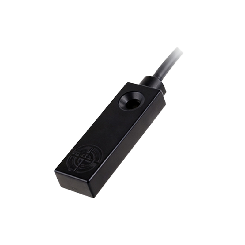
Electrical connection must be precise. Wire the sensor according to its datasheet diagram, paying close attention to the brown (24VDC+), blue (0VDC), black (output), and sometimes white (complementary output or function wire) color codes. Incorrect polarity can damage the device. For DC sensors, always include a protective fuse or circuit breaker in the line. Ensure the load (e.g., a PLC input, relay, or indicator lamp) is within the sensor's maximum current rating. A common issue is neglecting the residual current or leakage current of a sensor in its "OFF" state; this small current can sometimes keep a PLC input slightly active, requiring a bleeder resistor in parallel with the load.
The core of adjustment is setting the correct sensing distance and hysteresis. The rated sensing distance (Sn) is measured under ideal conditions with a standard target. In practice, factors like target material, size, temperature, and supply voltage influence the real operating point. Start by introducing the target object to the sensing face. Use the actual target material and size. Gradually move the target closer until the sensor's output switches (indicated by an LED on most models). Mark this "switch-on" point. Then, slowly move the target away until the output switches off. The distance between the "on" and "off" points is the hysteresis, a built-in feature to prevent output oscillation with a stationary target.
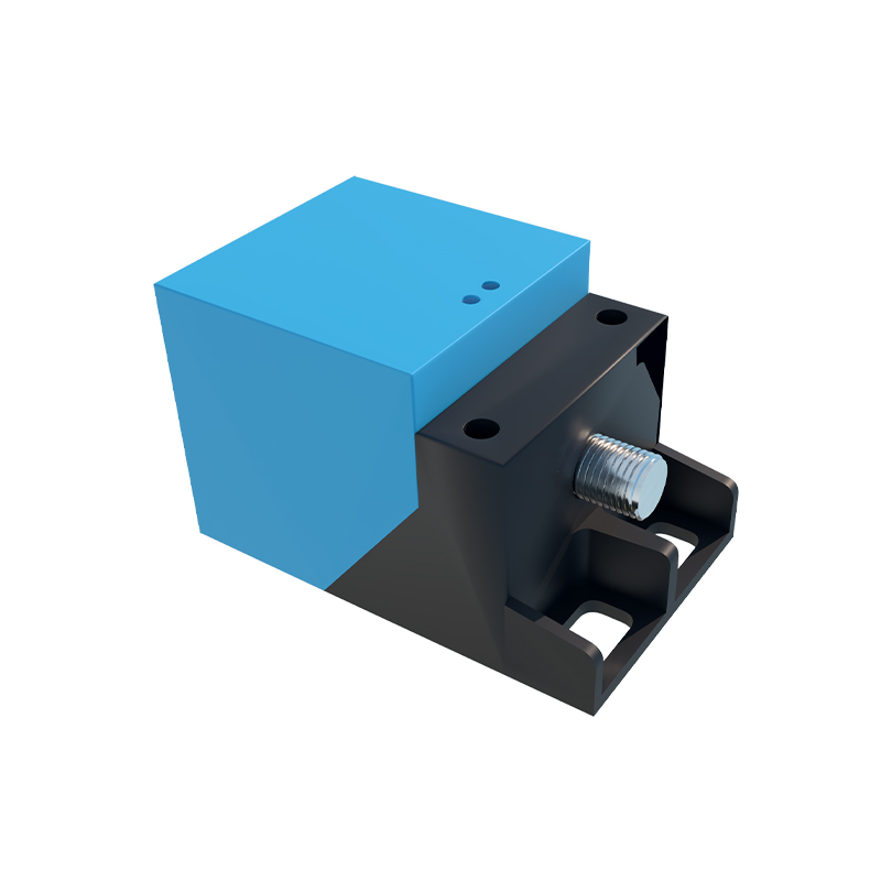
If the sensor has a potentiometer for sensitivity adjustment, this is the key tool. For a standard application, adjust the potentiometer so that the sensor triggers reliably when the target is at the desired position, with a safety margin of about 20-30% within the assured operating distance. For example, if the target needs to be detected at 8mm, ensure the sensor switches on at 9mm and off at 7mm. This margin compensates for mechanical wear, temperature drift, and minor misalignments. For applications detecting different materials or ignoring certain objects (like a small fastener while sensing a large metal pallet), the potentiometer allows you to fine-tune the threshold. Turn it clockwise (usually) to increase sensitivity and counter-clockwise to decrease it. Make adjustments in small increments.
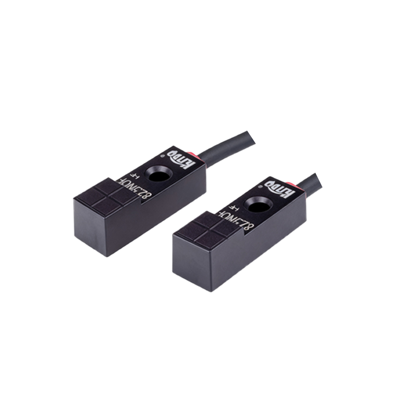
After adjustment, rigorous testing under real or simulated operating conditions is non-negotiable. Cycle the target repeatedly at the maximum operational speed. Test with potential interfering objects nearby. Monitor the sensor's output with an oscilloscope or a PLC's diagnostic tools to ensure clean, bounce-free switching. Check for the effects of temperature variation if the environment is not stable. For critical safety applications, such as in guarding systems, regular verification of the sensing function and adjustment is mandatory as part of a preventative maintenance schedule.
Common pitfalls to avoid include ignoring electrical noise in high-interference environments (use shielded cables and proper grounding), assuming all metals trigger inductive sensors equally (steel is best, aluminum and copper have reduced ranges), and overlooking the