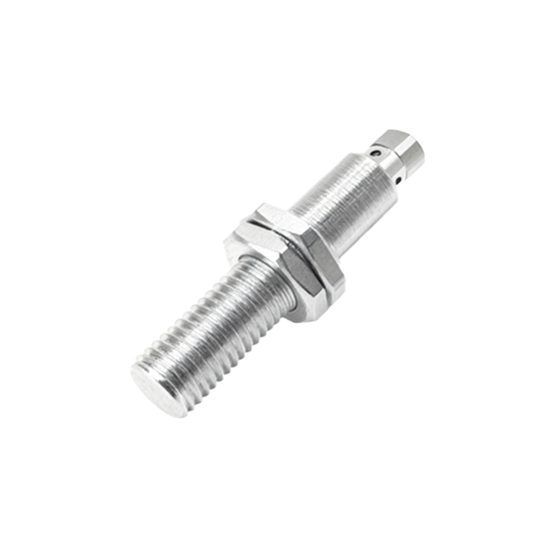
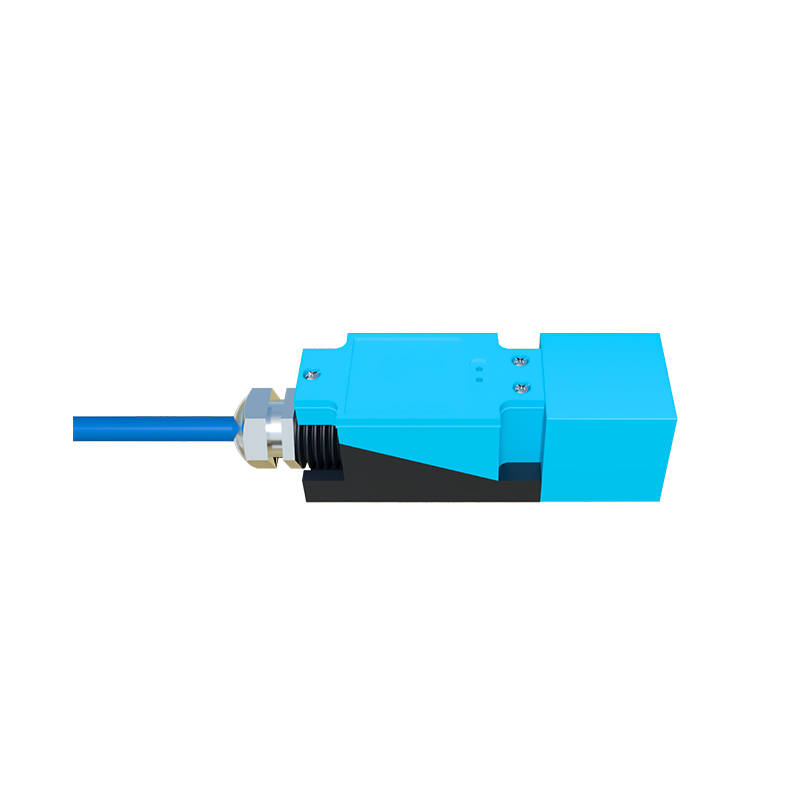
Proximity sensors are critical components in modern industrial automation, providing non-contact detection of objects with high reliability and precision. Proper parameter setup is essential to ensure optimal performance, minimize false triggers, and extend sensor lifespan. This guide outlines key parameters and best practices for configuring inductive, capacitive, and ultrasonic proximity sensors in industrial applications.
First, understand the sensor type. Inductive sensors detect metallic objects, capacitive sensors respond to both metallic and non-metallic materials, and ultrasonic sensors use sound waves for detection. Each type has unique parameter considerations. Begin by verifying the sensing range specified in the datasheet. The effective sensing distance can be influenced by factors such as target material, size, and environmental conditions. For inductive sensors, the sensing range varies with the metal type—steel typically offers the longest range, while aluminum or copper may reduce it by up to 60%. Adjust the sensing distance setting to account for these variations, ensuring a safety margin of 10-20% to prevent unintended activation due to target positioning tolerances.
Next, configure the output mode. Proximity sensors commonly feature digital outputs (e.g., NPN or PNP) or analog outputs (e.g., 4-20 mA or 0-10 V). Select the output type based on the control system requirements. For digital outputs, set the switching function to normally open (NO) or normally closed (NC) to match the logic of your application. If using analog outputs, calibrate the scaling to correspond accurately to the measured distance or presence. Ensure the load current does not exceed the sensor’s rated capacity to avoid damage.
Hysteresis is another vital parameter. It defines the difference between the switch-on and switch-off points, preventing rapid toggling when a target is near the detection threshold. Adjust hysteresis based on application stability needs—typically, a setting of 5-15% of the sensing range is effective for most scenarios. For example, in vibrating environments, increase hysteresis to reduce false signals.
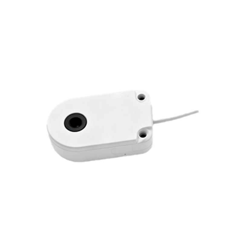
Response time must be tuned to match process speed. Proximity sensors can have response times from microseconds to milliseconds. In high-speed applications, such as conveyor systems, set a faster response to detect objects accurately without delay. However, in noisy electrical environments, slightly increase the response time to filter out interference, balancing speed and noise immunity.
Environmental factors require careful adjustment. Temperature fluctuations, humidity, and contaminants like dust or oil can affect sensor performance. Many sensors feature temperature compensation or IP-rated enclosures. Set parameters to account for operating conditions—for instance, in high-temperature settings, reduce the sensing range slightly to compensate for material expansion. For capacitive sensors, adjust sensitivity to avoid false triggers from background materials or moisture.
Finally, implement routine calibration and testing. Use a target of the correct material and size to verify detection consistency. Document parameter settings for future reference and maintenance. By following these steps, engineers can optimize proximity sensor setups, enhancing system efficiency and reducing downtime.