In industrial automation and control systems, proximity sensors are indispensable components for non-contact object detection. A common and critical issue faced by maintenance engineers and technicians is the "proximity sensor light not on" scenario. This illuminated indicator, typically an LED, serves as the primary visual cue for the sensor's operational status—power presence, output activation, and fault indication. When this light fails to illuminate under expected conditions, it initiates a systematic diagnostic process to restore functionality and prevent costly downtime.
The absence of the indicator light can stem from multiple root causes, ranging from simple wiring errors to complex internal failures. A structured, step-by-step troubleshooting approach is paramount. The first and most fundamental step is to verify the power supply. Ensure that the correct voltage (e.g., 10-30V DC for most DC sensors, or 90-250V AC for AC types) is present at the sensor's supply terminals using a reliable multimeter. Check for proper polarity for DC sensors. Simultaneously, inspect the integrity of the fuse or circuit breaker in the supply line. A tripped breaker or blown fuse is a frequent culprit.
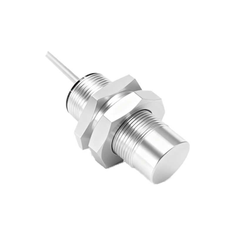
Following power confirmation, examine the electrical connections. Loose terminal screws, corroded contacts, or damaged cables can interrupt both power and signal paths. Tighten all connections and inspect the cable for any visible signs of crushing, cutting, or insulation damage. Pay special attention to the cable gland entry point, a common failure area due to stress. For sensors with quick-disconnect connectors, ensure they are fully seated and clean.
Next, assess the load and wiring configuration. A proximity sensor is typically connected in series with a load (e.g., a PLC input, relay coil). Verify that the load is functional and its impedance is within the sensor's specified rating. An open-circuit load or a short circuit can prevent the sensor from operating correctly. For 3-wire sensors, confirm the correct connection of the brown wire (positive/+), blue wire (negative/- or common), and black wire (output). For 2-wire AC/DC sensors, ensure they are wired in series with the load and power supply correctly.
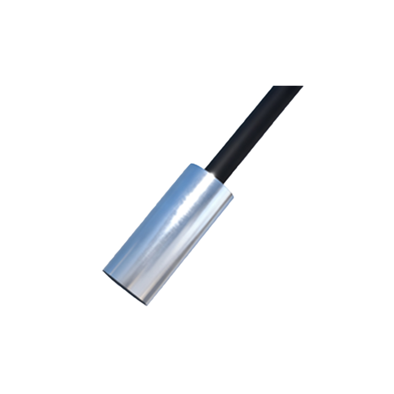
The sensing environment itself can be a factor. Metallic debris or accumulated dust on the sensor's active face can interfere with its electromagnetic or capacitive field, potentially causing internal circuitry to behave erratically, including disabling the indicator. Thoroughly clean the sensing face. Also, verify the target specifications: is it the correct material (ferrous/non-ferrous for inductive sensors), is it within the rated sensing distance, and is it of sufficient size? An out-of-range or unsuitable target will not trigger the sensor.
If basic checks yield no results, perform an isolation test. Temporarily disconnect the sensor from its control circuit and connect it directly to a known-good power supply and a simple pilot lamp as a load. This bypasses potential issues in the machine's wiring or controller. If the sensor light operates normally in this isolated test, the problem lies externally in the original circuit or load. If it still fails, the sensor itself is likely faulty.
Internal failures can include damaged oscillator circuitry (in inductive sensors), broken components from voltage spikes or surges, or a failed LED indicator itself. While some modern sensors have diagnostic LEDs separate from the output indicator, a completely dark sensor often points to a lack of power reaching the internal electronics or a catastrophic internal fault. Consider environmental stressors: excessive vibration can break solder joints, extreme temperatures can degrade components, and exposure to moisture or corrosive chemicals can lead to internal corrosion.
Preventive maintenance is key to avoiding these issues. Implement regular inspection schedules to check sensor mounting integrity, cable condition, and environmental cleanliness. Use stable, regulated power supplies with surge protection. Ensure sensors are selected appropriately for the application, considering factors like sensing distance, target material, housing material (e.g., stainless steel for harsh environments), and IP rating for dust/water resistance.
In conclusion, a non-illuminating proximity sensor light is a clear call for diagnostic action. By methodically investigating power supply, connections, load, environment, and finally the sensor unit itself, engineers can efficiently pinpoint the failure cause. Documenting these failures and solutions contributes to a valuable knowledge base, speeding up future troubleshooting and reinforcing the reliability of the entire automated system. Always prioritize safety by locking out and tagging out equipment before beginning any electrical troubleshooting work.