In industrial automation and control systems, proximity switch sensors are critical components for detecting the presence or absence of objects without physical contact. Their reliability is paramount for ensuring smooth production flow, safety interlocks, and precise machine sequencing. A common and often perplexing issue encountered by maintenance engineers and technicians is the failure of a proximity sensor to trigger an alarm or change state when an object is within its sensing range. This silent failure can lead to production stoppages, quality defects, or even safety hazards. This article delves into the root causes of this problem and provides a systematic troubleshooting methodology.
The principle of operation for inductive and capacitive proximity sensors involves generating an electromagnetic or electrostatic field. When a target object enters this field, it causes a change in the oscillator's amplitude or frequency, which is then processed by the sensor's circuitry to switch the output state. A failure to alarm typically means this switching action does not occur, despite a valid target being present. The causes can be broadly categorized into sensor-related issues, target-related issues, wiring and power problems, and environmental/interference factors.
Sensor-Related Issues:

1. Incorrect Sensor Type or Model: Using an inductive sensor to detect a non-metallic object, or a capacitive sensor improperly tuned for the specific material, will result in no detection. Always verify the sensor's datasheet for its sensing principle and suitable target materials.
2. Sensor Failure: Internal electronic component failure, damage to the sensing face, or degradation over time can render the sensor inoperative. Physical inspection for cracks, dents, or discoloration is the first step.
3. Incorrect Sensing Range: Every sensor has a rated nominal sensing distance (Sn). Operating too close to or beyond this range can cause unreliable operation. The effective sensing distance can be reduced by factors like target material, size, and temperature. Ensure the target is well within the sensor's usable range.
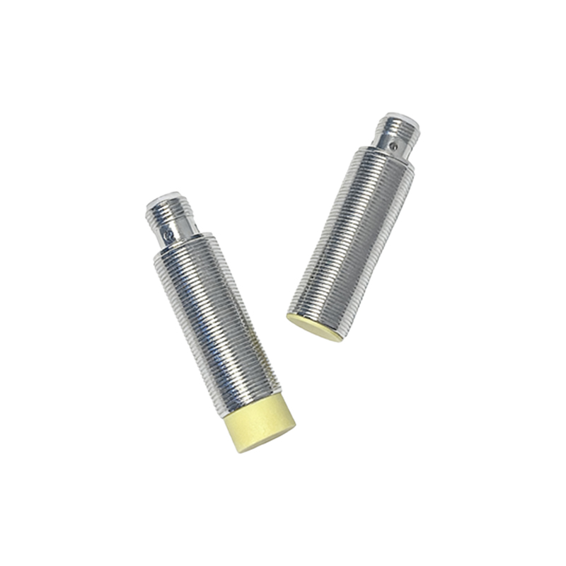
4. Output Configuration Mismatch: Proximity switches come in Normally Open (NO) and Normally Closed (NC) output types, as well as NPN (sinking) and PNP (sourcing) transistor configurations. Connecting an NPN sensor to a PLC input card configured for PNP sourcing, or misunderstanding the NO/NC logic, will lead to an apparent "no alarm" condition from the control system's perspective.
Target-Related Issues:
1. Unsuitable Target Material: Inductive sensors are primarily for metals, with different detection efficiencies for steel, aluminum, and copper. A thin aluminum foil might not be detected where a steel block would be. The target material must be compatible.
2. Insufficient Target Size: The target must be large enough to interact adequately with the sensor's field. A rule of thumb is that the target's diameter or side length should be equal to or greater than the sensor's sensing face diameter for standard sensing distances.
3. Incorrect Target Positioning: The target must approach the sensor correctly, typically perpendicular to the sensing face. Angular approaches or misalignment can significantly reduce the effective sensing distance.
Wiring and Power Supply Problems:
1. Incorrect Voltage Supply: Applying a voltage outside the sensor's specified range (e.g., 24VDC sensor with 12VDC) can cause under-performance or complete failure. Always check the supply voltage at the sensor's terminals under load.
2. Wiring Faults: Loose connections, broken wires, or short circuits are frequent culprits. Use a multimeter to check for continuity, correct voltage, and the absence of shorts. Pay special attention to the shield wire if present.
3. Overload or Short Circuit Protection Activation: If the sensor's output has been short-circuited or connected to a load exceeding its current rating, internal protection may have tripped, disabling the output. Disconnect power and load to reset.
4. Incorrect Load Connection: The load (e.g., PLC input, relay coil) must be connected in series with the sensor's output. Verify the wiring diagram for 2-wire, 3-wire, or 4-wire sensors.
Environmental and Interference Factors:
1. Sensor Mounting: Metal-to-metal mounting (flush mounting) of an unshielded sensor can decrease its sensing range. Non-flush mounting or using shielded sensors in metal housings is often necessary.
2. Adjacent Interference: The presence of other sensors, strong magnetic fields, welding equipment, or large motors in close proximity can cause electromagnetic interference (EMI), leading to erratic behavior or desensitization. Increase separation distance or use sensors with robust EMI immunity.
3. Contamination: Accumulation of metal chips, dust, oil, or coolant on the sensing face can insulate