Magnetic proximity sensors are fundamental components in modern industrial automation, offering non-contact detection of ferromagnetic objects. Their robust design, immunity to environmental contaminants, and long operational life make them indispensable in machinery, material handling, and safety systems. Understanding their wiring principles is crucial for ensuring reliable operation and system integration.
At its core, a magnetic proximity sensor operates by detecting the presence or absence of a magnetic field, typically from a permanent magnet attached to a moving target. The sensor itself contains a reed switch or a solid-state Hall-effect element. When the external magnetic field reaches a certain threshold, it triggers a change in the sensor's internal state. This change is electrically manifested as the opening or closing of a switching circuit.
The wiring configuration is primarily defined by the sensor's output type and the electrical load it controls. The three principal wiring types are:
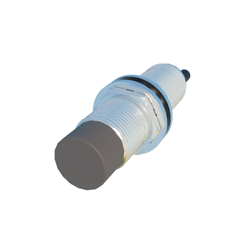
1. 2-Wire DC Sensors (Load in Series): These are the simplest to wire, functionally similar to a mechanical switch. They have two terminals connected in series with the load (e.g., a PLC input, relay coil) and the power supply. The sensor consumes a small "leakage" or "off-state" current even when inactive. It is critical to ensure this current (typically<1.5 mA) is below the minimum operating current of the load to prevent false triggering. The load must always be connected for the sensor to function. Polarity is not a concern for AC 2-wire sensors, but for DC versions, correct polarity must be observed.
2. 3-Wire DC Sensors (PNP or NPN Output): This is the most common configuration in DC systems, offering superior performance. These sensors have three wires: supply positive (brown/red), supply negative (blue/black), and the signal output (black/white).
PNP (Sourcing) Output: The output switch is connected between the positive supply and the output terminal. When activated, the sensor sources current to the load. The load is connected between the output terminal and the negative supply.
NPN (Sinking) Output: The output switch is connected between the output terminal and the negative supply. When activated, the sensor sinks current from the load. The load is connected between the positive supply and the output terminal.
Mismatching PNP and NPN sensors with the control system (e.g., PLC sinking vs. sourcing input cards) is a common installation error that prevents operation.
3. 4-Wire DC Sensors (Dual Output or NO+NC): These sensors provide both a Normally Open (NO) and a Normally Closed (NC) output from a single device, often in a PNP or NNP configuration. They offer wiring flexibility for control circuits requiring complementary signals or fail-safe logic.
Key Wiring Considerations:
Power Supply: Always use a stable, regulated DC power supply within the sensor's rated voltage range (e.g., 10-30 VDC). Ripple and voltage spikes can cause erratic behavior.
Load Compatibility: The sensor's maximum switching current and voltage must not be exceeded. For inductive loads like relay coils, use protective components such as flyback diodes or RC snubber circuits to suppress voltage transients that can damage the sensor's output transistor.
Shielding and Routing: In electrically noisy environments, use shielded cables and route sensor wires away from power cables, motor drives, and high-current conductors to prevent electromagnetic interference (EMI). Ground the shield at the control panel end only.
Short-Circuit and Overload Protection: While many sensors have built-in protection, incorporating an external fuse (e.g., 1-2A) in the supply line is a recommended best practice.
Wiring Diagrams: Always consult the manufacturer's datasheet for the specific wiring diagram, terminal designations, and color codes, as conventions can vary.
Proper wiring is not merely a matter of connectivity; it is integral to system performance and longevity. Incorrect wiring can lead to sensor failure, intermittent operation, or damage to the controller. A methodical approach—verifying sensor type (PNP/NPN), supply polarity, load characteristics, and implementing noise suppression—forms the foundation of a robust and reliable automated system. As industrial networks evolve, the principles of correctly interfacing these binary sensors with higher-level controls remain a constant and essential engineering skill.