In the realm of industrial automation and control systems, proximity sensors are indispensable components for non-contact detection of metallic or non-metallic objects. However, a critical electrical phenomenon often overlooked during system design and sensor selection is inrush current. This transient surge of current, which occurs at the moment of power application, can have significant implications for system reliability, component longevity, and overall electrical safety. This article delves into the intricacies of inrush current specific to proximity sensors, exploring its root causes, potential consequences, and effective strategies for mitigation.
At its core, inrush current is a momentary spike that far exceeds the sensor's steady-state operating current. For inductive proximity sensors, the primary culprit is the internal ferrite-cored coil. Upon energization, the coil presents a very low impedance until the magnetic field is fully established. This period, though brief—typically lasting from a few microseconds to several milliseconds—allows a large current to flow as the internal capacitance charges and the coil's magnetic field saturates. The magnitude of this current can be 10 to 100 times the sensor's nominal operating current. Capacitive and ultrasonic proximity sensors also experience inrush, though often to a lesser degree, primarily due to the charging of internal filter capacitors and the initial power surge required by the oscillator or transducer circuits.
The impacts of unmanaged inrush current are multifaceted and can cascade through an entire control system. The most immediate risk is to the power supply unit. Repeated high-current surges can stress the power supply's components, leading to premature failure or triggering overcurrent protection mechanisms, causing unexpected system shutdowns. Furthermore, the voltage dip caused by the inrush current can affect other sensitive devices connected to the same power rail, a phenomenon known as "brownout," which can lead to erratic behavior or resets in PLCs, controllers, or other sensors.
From a sensor perspective, the thermal stress induced by each inrush event, though brief, contributes to cumulative wear on internal components like the oscillator IC, output transistor, and voltage regulator. Over time, this accelerates aging and increases the likelihood of premature sensor failure. Additionally, the electromagnetic interference (EMI) generated by the rapid current change can couple into nearby signal lines, potentially causing false triggering or communication errors in networked systems.
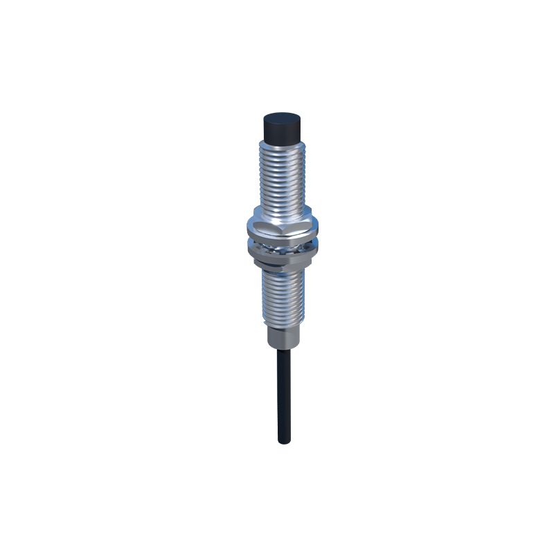
Addressing inrush current requires a systematic approach, beginning at the sensor selection stage. Many modern proximity sensor manufacturers specify inrush current values in their datasheets, often denoted as I_inrush or I_peak. Comparing these specifications is crucial. Sensors with built-in inrush current limitation circuits, such as soft-start features or series resistors integrated into the input stage, are highly desirable for applications involving multiple sensors or sensitive electronics.
At the system design level, several proven mitigation strategies exist. The most common is the use of inrush current limiters (ICLs), which are negative temperature coefficient (NTC) thermistors placed in series with the sensor's power line. When cold, the NTC presents a high resistance, limiting the initial current flow. As it heats up due to the current, its resistance drops, allowing normal operation. A critical design consideration is the thermal recovery time of the NTC; if power is cycled rapidly, the NTC may still be hot and fail to limit the subsequent inrush. For applications requiring frequent cycling, a fixed resistor in parallel with a relay or a semiconductor-based active inrush limiter may be a more suitable, albeit more complex, solution.
Proper power supply sizing is another fundamental countermeasure. The power supply's current rating should account not just for the sum of all sensors' steady-state currents, but also for the combined inrush currents, especially if multiple sensors are powered simultaneously. Staggered power-up sequences, controlled by a PLC or sequencer, can prevent all sensors from energizing at the same instant, thereby distributing the inrush load over time.
Finally, ensuring robust and low-impedance wiring with proper gauge reduces line resistance and inductance, which can exacerbate voltage drops during the inrush event. Implementing local decoupling capacitors near sensor clusters can also provide a temporary local energy reservoir, helping to stabilize the supply voltage during the transient period.
In conclusion, while proximity sensors are designed for robustness, the phenomenon of inrush current presents a tangible engineering challenge. By understanding its electrical origins and systemic impacts, engineers and system integrators can make informed decisions. Proactive measures—including careful sensor specification, strategic use of current-limiting devices, adequate power supply design, and thoughtful system layout—are essential for building resilient, reliable, and long-lasting automation systems. Ignoring inrush current is a gamble with system uptime, whereas managing it effectively is a hallmark of professional, forward-thinking design.