Proximity switch sensors are fundamental components in modern industrial automation, serving as the primary interface for non-contact object detection and, critically, for high-speed counting applications. Understanding the counting principles of these sensors is essential for designing reliable and efficient automated systems. Unlike mechanical limit switches, proximity sensors detect the presence or absence of a target object without physical contact, using electromagnetic fields, light, or sound. This non-contact nature is the cornerstone of their counting capability, enabling high-speed, wear-free operation essential for production lines, packaging machinery, and material handling systems.
The core counting principle revolves around the sensor's ability to generate a discrete electrical signal—typically a voltage pulse—each time a target object enters its sensing range. This pulse is then transmitted to a counting device, such as a Programmable Logic Controller (PLC), a dedicated counter module, or a frequency converter. The process can be broken down into three sequential stages: detection, signal conditioning, and pulse processing.
First, in the detection stage, the sensor's internal oscillator generates a high-frequency electromagnetic field (for inductive sensors) or emits a beam of light (for photoelectric sensors). When a metallic target (for inductive) or any opaque object (for photoelectric) disrupts this field or beam, it causes a change in the sensor's internal circuit state. For an inductive proximity sensor, the eddy currents induced in the metal target dampen the oscillation amplitude. This damping is detected by a threshold circuit, which triggers a state change. Similarly, a photoelectric sensor's receiver detects a drop in light intensity when the beam is interrupted.
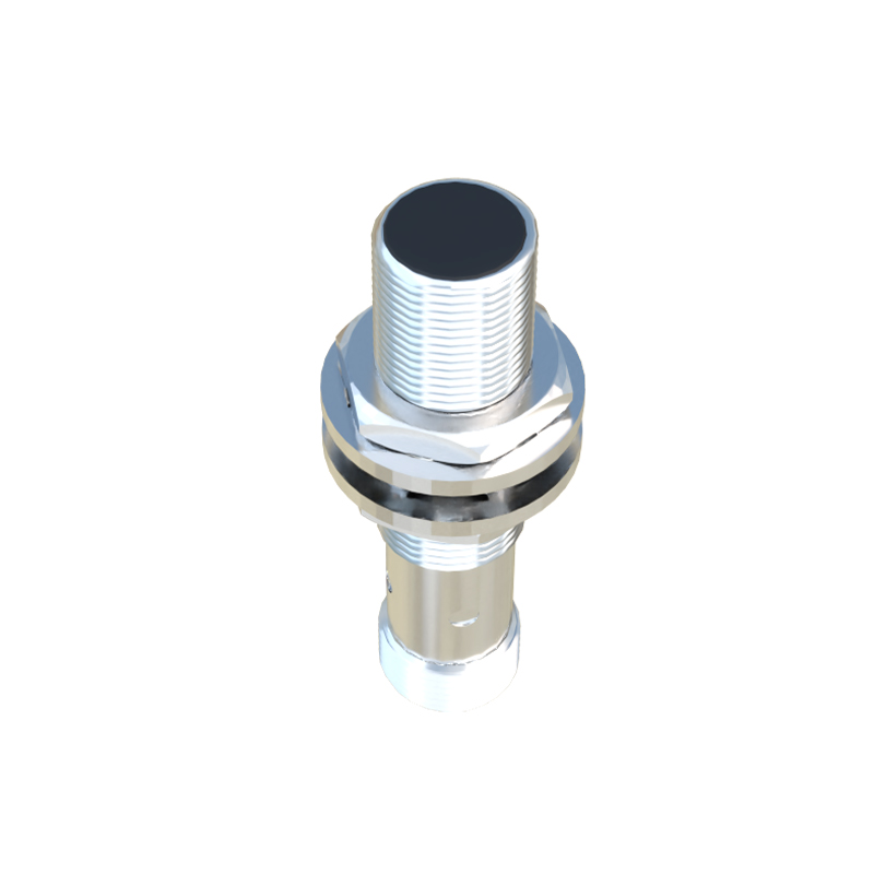
Second, the signal conditioning stage is crucial for reliable counting. The raw signal from the sensing element is processed internally. The sensor's electronics include components like Schmitt triggers to provide hysteresis, preventing signal chatter or multiple counts from a single object due to vibration or minor positional fluctuations. The output is then converted into a clean, sharp digital signal. Common output types include NPN (sinking) or PNP (sourcing) transistor outputs for DC sensors, and solid-state or relay outputs for AC models. This clean, binary signal (ON/OFF, 24V/0V) is the standardized "pulse" sent to the counter.
Finally, the pulse processing stage occurs in the external counter or PLC. The controller is programmed to increment its count register each time it receives a rising edge (or sometimes a falling edge) of the pulse from the sensor. The accuracy of the count depends heavily on the relationship between the sensor's performance parameters and the application's physical requirements. Key parameters include:
Sensing Distance: The nominal range at which the sensor can reliably detect a standard target. Objects must pass within this range to be counted.
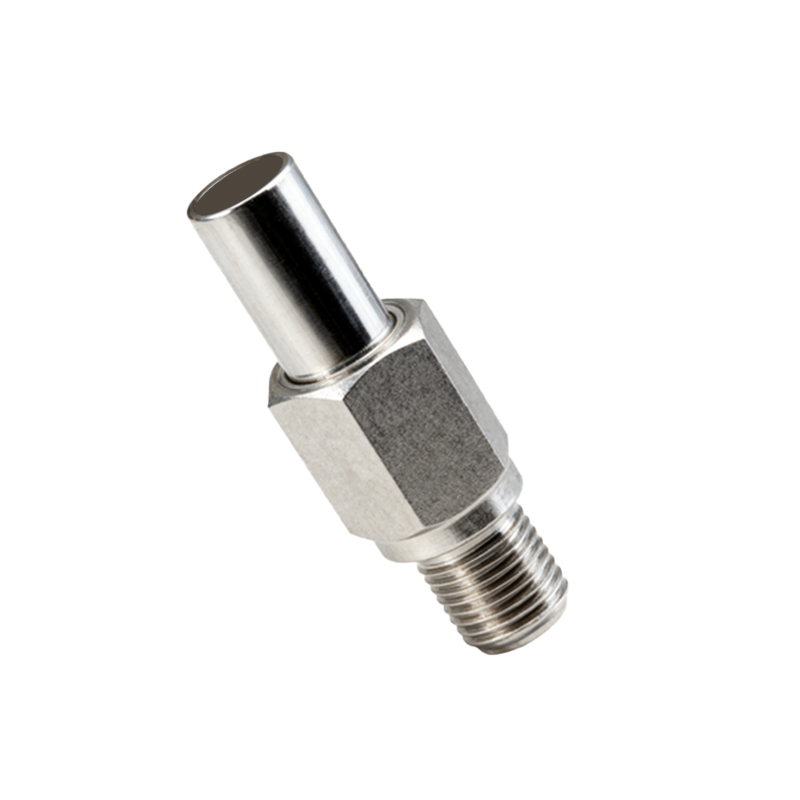
Response Time: The time delay between the target entering the sensing field and the output switching. A fast response time (often in microseconds for inductive sensors) allows for counting of very small or very fast-moving objects.
Switching Frequency: The maximum number of output cycles (ON-OFF-ON) the sensor can perform per second. This directly limits the maximum countable object speed. Exceeding this frequency will result in missed counts.
Hysteresis: The difference between the switch-on point (when the target approaches) and the switch-off point (when it recedes). This prevents output oscillation when a target is positioned at the exact edge of the sensing range.
For accurate counting, the application must satisfy a critical timing condition. The time an object spends within the sensor's effective sensing zone must be greater than the sensor's response time. Furthermore, the time between two successive objects must be greater than the sensor's output pulse width plus its recovery time to ensure two distinct pulses are generated. Failure to meet these conditions leads to missed counts or double counts.
Advanced counting systems often employ two sensors in a specific configuration to determine the direction of movement, which is vital for applications like bidirectional conveyor lines or inventory in/out tracking. By monitoring the sequence in which the two sensors are triggered (Sensor A then B, or B then A), the PLC logic can increment or decrement a counter accordingly.
In summary, the counting function of a proximity switch sensor is an elegant integration of physics, electronics, and control logic. Its reliability hinges on selecting a sensor with appropriate technical specifications—response time, switching frequency, and sensing distance—that match the physical parameters of the target objects and their speed. Proper installation, alignment, and integration with the control system are equally vital to transform a simple detection event into a precise and trustworthy count, forming the backbone of data acquisition in automated production and logistics.