Building a laser sensor for industrial automation is a sophisticated yet rewarding project for electrical engineers and hobbyists. This guide provides a step-by-step approach to creating a basic laser-based proximity or presence detection sensor, commonly used in manufacturing lines, safety systems, and robotics. The core principle involves emitting a focused laser beam and detecting its reflection or interruption to trigger an electrical signal.
The first critical component is the laser diode. For most industrial sensing applications, a Class 2 or Class 3R visible red laser diode (e.g., 650nm wavelength) with a low power output (1-5mW) is sufficient and safe for prototyping. These are readily available and inexpensive. The key is to pair it with a constant current driver circuit to ensure stable output and prevent burnout from voltage spikes. A simple driver can be built using an LM317 voltage regulator configured as a current regulator. Always incorporate appropriate current-limiting resistors based on your diode's specifications.
Next is the photodetector. A phototransistor or a photodiode is typically used. For better ambient light immunity, especially in noisy industrial environments, consider using a sensor matched to the laser's wavelength. Many components have built-in daylight filters. The detector must be placed in a housing that minimizes stray light. For a basic through-beam sensor setup, the emitter and detector are placed opposite each other; breaking the beam triggers the output. For a reflective (retro-reflective) setup, both units are side-by-side, and the beam bounces off a reflector or the target itself.
Signal conditioning is where the engineering challenge lies. The signal from the photodetector is weak and analog. You need a comparator circuit (using an IC like the LM393) to convert it into a clean digital HIGH/LOW signal. The comparator compares the detector's voltage against a preset threshold, adjustable via a potentiometer. This allows you to fine-tune the sensor's sensitivity to ignore dust or minor reflections and only react to the intended target. For pulsed operation to further combat ambient light, you can modulate the laser driver with a 555 timer circuit and synchronously demodulate the received signal.
The output stage interfaces with control systems. A simple transistor (like a 2N2222) can switch a relay or an optocoupler to provide an isolated digital output compatible with PLCs (Programmable Logic Controllers) or microcontrollers. For direct microcontroller interfacing (e.g., Arduino, Raspberry Pi), the digital signal from the comparator can be fed directly into a GPIO pin. Don't forget to add status LEDs for visual feedback on power and detection state.
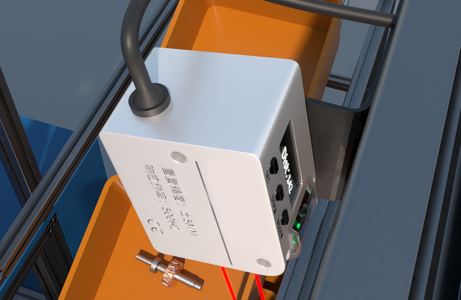
Mechanical design and calibration are crucial. Build a robust enclosure, typically from aluminum, to protect the electronics and ensure precise alignment of the optical components. Use set screws for fine adjustment. The housing should have conduits for power and output cables. Calibration involves powering the unit, aiming the laser, and adjusting the sensitivity potentiometer until the output toggles reliably when an object enters the sensing field. Always perform a safety check: never look directly into the laser beam, and ensure the housing prevents accidental exposure.

While this DIY sensor is excellent for learning and light-duty applications, remember that commercial-grade laser sensors offer higher precision, IP-rated enclosures, and advanced diagnostics. However, understanding the build process deepens your knowledge of optoelectronics, signal processing, and industrial control integration, making you a more versatile engineer in the field of factory automation and smart systems.
The first critical component is the laser diode. For most industrial sensing applications, a Class 2 or Class 3R visible red laser diode (e.g., 650nm wavelength) with a low power output (1-5mW) is sufficient and safe for prototyping. These are readily available and inexpensive. The key is to pair it with a constant current driver circuit to ensure stable output and prevent burnout from voltage spikes. A simple driver can be built using an LM317 voltage regulator configured as a current regulator. Always incorporate appropriate current-limiting resistors based on your diode's specifications.
Next is the photodetector. A phototransistor or a photodiode is typically used. For better ambient light immunity, especially in noisy industrial environments, consider using a sensor matched to the laser's wavelength. Many components have built-in daylight filters. The detector must be placed in a housing that minimizes stray light. For a basic through-beam sensor setup, the emitter and detector are placed opposite each other; breaking the beam triggers the output. For a reflective (retro-reflective) setup, both units are side-by-side, and the beam bounces off a reflector or the target itself.
Signal conditioning is where the engineering challenge lies. The signal from the photodetector is weak and analog. You need a comparator circuit (using an IC like the LM393) to convert it into a clean digital HIGH/LOW signal. The comparator compares the detector's voltage against a preset threshold, adjustable via a potentiometer. This allows you to fine-tune the sensor's sensitivity to ignore dust or minor reflections and only react to the intended target. For pulsed operation to further combat ambient light, you can modulate the laser driver with a 555 timer circuit and synchronously demodulate the received signal.
The output stage interfaces with control systems. A simple transistor (like a 2N2222) can switch a relay or an optocoupler to provide an isolated digital output compatible with PLCs (Programmable Logic Controllers) or microcontrollers. For direct microcontroller interfacing (e.g., Arduino, Raspberry Pi), the digital signal from the comparator can be fed directly into a GPIO pin. Don't forget to add status LEDs for visual feedback on power and detection state.
Mechanical design and calibration are crucial. Build a robust enclosure, typically from aluminum, to protect the electronics and ensure precise alignment of the optical components. Use set screws for fine adjustment. The housing should have conduits for power and output cables. Calibration involves powering the unit, aiming the laser, and adjusting the sensitivity potentiometer until the output toggles reliably when an object enters the sensing field. Always perform a safety check: never look directly into the laser beam, and ensure the housing prevents accidental exposure.
While this DIY sensor is excellent for learning and light-duty applications, remember that commercial-grade laser sensors offer higher precision, IP-rated enclosures, and advanced diagnostics. However, understanding the build process deepens your knowledge of optoelectronics, signal processing, and industrial control integration, making you a more versatile engineer in the field of factory automation and smart systems.