In industrial automation and control systems, proximity sensors play a critical role in detecting the presence or absence of objects without physical contact. Among the various technical specifications, the concept of "0V" in proximity sensor wiring and operation is fundamental yet often misunderstood. This article explores the significance of 0V in proximity sensor circuits, its practical implications, and best practices for implementation.
Proximity sensors, whether inductive, capacitive, or photoelectric, typically require a power supply to function. In DC-powered sensors, the common configuration involves two wires for power and a third for the output signal. Here, 0V refers to the ground or negative terminal of the power supply. It serves as the reference point for voltage levels in the circuit. When a sensor detects a target, its output transistor switches, connecting the output line either to the supply voltage (e.g., 24V) or to 0V, depending on the sensor type (sourcing or sinking). In sinking (NPN) sensors, the output pulls down to 0V when active, completing the circuit to ground. This allows current to flow from the load (like a PLC input) through the sensor to 0V. Conversely, sourcing (PNP) sensors connect the output to the positive supply when active, with 0V serving as the return path.
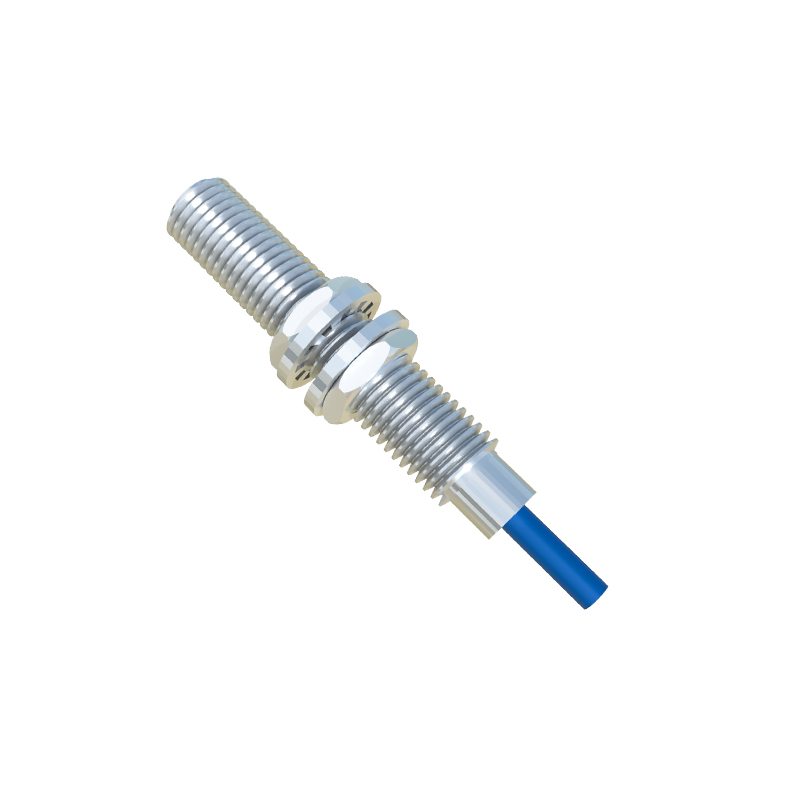
The 0V reference must be stable and consistent across the system. Voltage fluctuations or ground loops can cause false triggering or sensor malfunction. In practice, engineers must ensure that the 0V lines from the power supply, sensor, and controller are properly bonded. Shielded cables are often used for noise immunity, with shields grounded at one end to 0V to prevent interference. Additionally, in multi-sensor setups, a common 0V bus bar or star-point grounding is recommended to avoid potential differences.
Another key aspect is the relationship between 0V and sensor output types. For sinking outputs, the load is connected between the positive supply and the sensor output. When the sensor activates, it connects the output to 0V, turning on the load. This configuration is common in regions like Europe and Asia. In sourcing outputs, the load is between the sensor output and 0V, with the sensor providing positive voltage when active—a standard in North America. Miswiring these configurations, such as connecting a sinking sensor to a sourcing input without proper interface, can lead to damage or failure.
Furthermore, 0V plays a role in diagnostic features. Some advanced proximity sensors include short-circuit protection or status indicators referenced to 0V. For instance, a fault condition might pull a diagnostic pin to 0V, signaling an issue to the control system. Understanding this helps in troubleshooting and maintaining system reliability.
In summary, 0V in proximity sensors is not merely a passive connection but an active part of the detection and control loop. Proper handling of 0V ensures accurate sensing, reduces downtime, and enhances safety. Engineers should always refer to manufacturer datasheets, adhere to local electrical codes, and test circuits under realistic conditions. As automation evolves, with trends like IIoT and smart sensors, the principles of solid grounding and clear voltage referencing remain timeless for robust system design.