In industrial automation and machinery, proximity sensors are indispensable components for non-contact detection of objects. They play critical roles in positioning, counting, safety interlocks, and speed monitoring. When a machine malfunctions or a production line halts unexpectedly, a faulty proximity sensor is often a prime suspect. However, simply replacing a sensor without proper diagnosis can be costly and may not solve the underlying issue. This guide provides a systematic, engineer-approved approach to testing a proximity sensor suspected of failure.
1. Initial Safety and Preparatory Checks
Before any testing begins, adhere to strict lockout/tagout (LOTO) procedures. De-energize and isolate the equipment to prevent accidental startup or electrical shock. Once safe, gather necessary tools: a digital multimeter (DMM), the sensor's datasheet, and possibly an oscilloscope for advanced diagnostics. Visually inspect the sensor for obvious damage—cracks in the housing, bent or broken sensing face, corrosion on the connector, or severed cables. Check the mechanical mounting; loose brackets can misalign the sensor, causing erratic operation. Ensure the sensing face is clean and free from debris, metal shavings, or thick grease that could interfere with detection.
2. Understanding Your Sensor Type
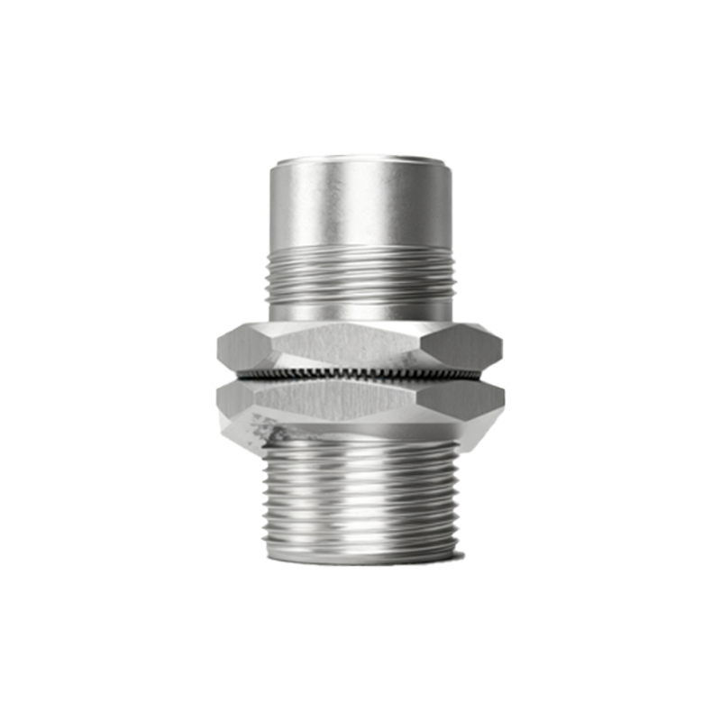
Correct testing hinges on identifying the sensor type. The two main categories are inductive (detects metals) and capacitive (detects various materials including liquids and plastics). Furthermore, you must know its output configuration:
PNP (Sourcing): Outputs a positive voltage (+V) when activated.
NPN (Sinking): Outputs 0V (ground) when activated.
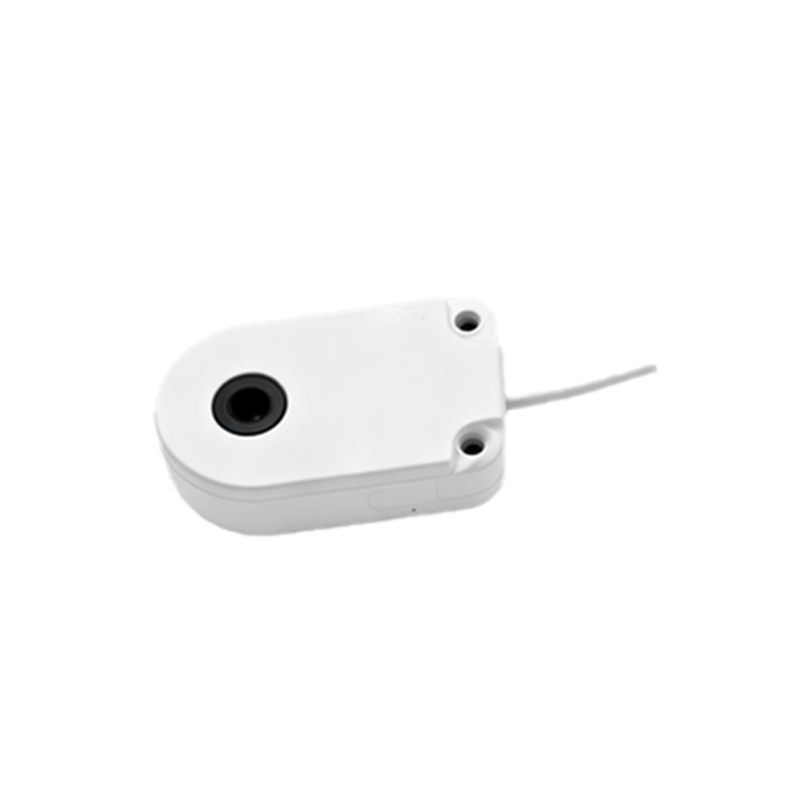
Analog Output: Provides a variable voltage or current signal proportional to distance.
NAMUR (Intrinsically Safe): Used in hazardous areas; requires a separate amplifier.
Consult the sensor's nameplate and datasheet for its model number, operating voltage (typically 10-30V DC or 90-250V AC), output type, and sensing range.
3. Power Supply Verification
A significant percentage of "sensor failures" are actually power issues. With the multimeter set to DC voltage (for DC sensors), reconnect power to the system or sensor circuit. Carefully measure the voltage between the sensor's positive (usually brown wire) and negative (usually blue wire) supply terminals. Ensure the voltage is stable and within the specified range (e.g., 24V DC ±10%). An unstable or low voltage indicates a problem with the power supply, wiring, or PLC power card, not the sensor itself.
4. Testing the Output Signal (Discrete Sensors)
For standard 3-wire PNP or NPN sensors:
Identify Wires: Common color codes are Brown (+V), Blue (0V/Common), and Black (Output). Always verify with the datasheet.
Setup DMM: Set the DMM to measure DC voltage. Connect the black probe to the Blue (0V) wire.
Test State: First, test with no target present in the sensing range. The output voltage should be near 0V for a PNP sensor (off state) and near supply voltage for an NPN sensor (off state).
Activate Sensor: Introduce a valid target (a piece of metal for inductive sensors) within the specified sensing distance. For a PNP sensor, the voltage on the Black wire should now jump to near the supply voltage (+V). For an NPN sensor, it should drop to near 0V.
If the output does not switch states correctly, the sensor is likely faulty. Ensure the target is of the correct material and size, and that you are within the rated sensing distance—consider the reduction factor for different metals.
5. Testing Analog and Special Sensors
For analog sensors, use the DMM to measure the output (often wire color: black or white) relative to common (blue). As a target moves through the sensing range, the voltage (e.g., 0-10V) or current (e.g., 4-20mA) should change smoothly and proportionally. A fixed reading or a reading outside the possible range indicates a fault.
For 2-wire AC/DC sensors, they are wired in series with the load. Measure the voltage drop across the sensor when on; it should be low (a few volts). A high voltage drop indicates excessive internal resistance.
NAMUR sensors cannot be tested with a standard multimeter directly. Check the output current at the associated intrinsic safety barrier or amplifier, which should switch between two low-current states (typically 1-2mA and above 4mA).
6. Advanced Diagnostics with an Oscilloscope
If intermittent failures occur,