In industrial automation and control systems, proximity switches are indispensable components for non-contact object detection. A common and critical issue faced by maintenance engineers and system integrators is a weak or deteriorating sensor signal. This condition can lead to intermittent machine operation, false triggering, or complete system failure, resulting in costly downtime. Understanding the root causes and implementing systematic troubleshooting is paramount for ensuring operational reliability.
A weak signal from a proximity switch typically manifests as a reduced sensing distance, erratic on/off behavior, or a failure to trigger the PLC input module reliably. The output signal, whether NPN, PNP, or analog, does not reach the required voltage or current threshold for the control system. The primary culprits for this issue can be categorized into environmental factors, electrical issues, mechanical misalignment, and sensor degradation.
Environmental Interference and Contamination: Industrial environments are harsh. Accumulation of metallic dust, chips, or non-conductive debris on the active face of the sensor can severely attenuate the electromagnetic or capacitive field, reducing effective sensing range. For inductive sensors, ferrous dust is particularly problematic. Similarly, chemical splashes or oil coatings can form a barrier. Furthermore, strong electromagnetic interference (EMI) from nearby variable frequency drives (VFDs), welding equipment, or high-current cables can induce noise onto the sensor's signal lines, corrupting the output.
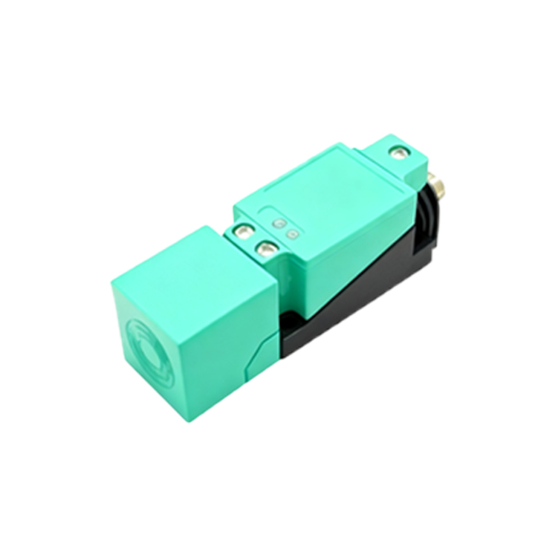
Electrical Supply and Wiring Problems: A stable power supply is the foundation of sensor performance. Voltage drops due to undersized wiring, long cable runs, or poor connections at terminal blocks can cause the sensor to operate below its specified voltage range (e.g., 10-30V DC), leading to a weak output. Ground loops or improper shielding of the signal cable is another major source of signal integrity loss. The shield must be grounded at only one end, typically the control panel end, to effectively drain noise. Loose connections, corroded contacts, or damaged cable insulation can introduce high resistance paths.
Mechanical and Installation Errors: The sensing performance is highly dependent on correct installation. Incorrect mounting, such as not flushing the sensor face properly or using non-recommended fasteners, can affect the field geometry. The presence of a metal background or adjacent sensors within their mutual interference range can also detune the sensor, causing a weaker effective signal. For all sensors, ensuring the target material, size, and approach angle are within specifications is crucial; a smaller or non-standard target will result in a reduced signal.
Sensor Degradation and Internal Failure: Proximity switches, though robust, have a finite lifespan. Internal oscillator circuit components can drift over time due to thermal cycling. The coil in an inductive sensor may partially degrade. Physical damage to the housing or face from impacts can misalign internal components. In such cases, the sensor may still function but with markedly reduced performance, indicating impending failure.
Systematic Troubleshooting Procedure:
1. Visual Inspection: Clean the sensor face thoroughly. Check for physical damage, correct mounting, and proper target alignment. Verify ambient temperature is within specs.
2. Electrical Measurement: Use a digital multimeter to measure the supply voltage at the sensor's terminals under load. Check for DC ripple or AC noise on the supply line. Measure the output signal voltage/current directly at the sensor when a target is present and absent. Compare with datasheet values.
3. Wiring and Grounding Audit: Inspect all connections for tightness and corrosion. Verify cable integrity and ensure the shield is properly terminated (single-point ground). Temporarily use a dedicated, shielded cable run from the sensor to the PLC to rule out wiring issues.
4. Isolation Test: Temporarily remove the sensor from its environment to test on a known-good target in a clean, electrically quiet bench setup. This helps isolate environmental factors.
5. Swap Test: Replace the suspect sensor with a known-good unit of the same model. If the problem resolves, the original sensor is faulty.
6. Load Check: Ensure the sensor's output is not overloaded. Check the input impedance of the PLC card or the current draw of the relay/load being driven.
Preventive Measures: To mitigate weak signal issues, adopt a proactive maintenance schedule. Specify sensors with appropriate IP ratings for the environment. Use braided shielding or conduit for cables in high-EMI areas. Implement proper grounding schemes and use stable, regulated power supplies. Regularly clean sensor faces and audit electrical connections during planned downtime.
In conclusion, a weak proximity switch signal is a symptom with multiple potential causes. A methodical approach—starting from the simplest environmental checks, progressing through electrical verification, and culminating in component substitution—is the most efficient path to diagnosis and resolution. Ensuring proper selection, installation, and maintenance from the outset remains the most effective strategy for maximizing sensor lifespan and