In the realm of industrial automation and electrical control systems, proximity switch sensors stand as fundamental components for non-contact detection. Among the various types available, DCF (Direct Current Field) proximity switch sensors represent a specific and highly reliable technology. This article delves into the operational principles, key characteristics, application scenarios, and selection criteria for DCF proximity sensors, providing a thorough technical overview for electrical engineers and industry professionals.
At its core, a DCF proximity sensor is a type of inductive sensor. Unlike standard inductive sensors that generate an alternating electromagnetic field, DCF sensors operate using a direct current (DC) magnetic field. This fundamental difference in operation grants them unique advantages. The sensor contains an oscillator circuit that creates a DC magnetic field emanating from its active face. When a metallic object, specifically a ferromagnetic target (such as iron or steel), enters this static magnetic field, it causes a change in the field's characteristics. This change is detected by the sensor's evaluation circuitry, which subsequently triggers a switching signal—typically changing the state of its solid-state output (PNP or NPN). The key point is that only ferromagnetic materials can actuate a true DCF sensor; non-ferrous metals like aluminum, brass, or copper will not trigger a response.
The defining feature of DCF technology is its immunity to electromagnetic interference (EMI) and its ability to ignore adjacent metallic structures. In environments saturated with strong electromagnetic noise from welding equipment, frequency converters, or large motors, standard AC inductive sensors can experience false triggering or reduced sensing ranges. The DC magnetic field of a DCF sensor is largely unaffected by such interference, ensuring stable and reliable operation. Furthermore, a significant benefit is the sensor's "immunity to flanking metal." This means that a DCF sensor can be mounted flush in a metal bracket or directly on a metal surface without the sensor's field being distorted or its sensing range diminished. Standard inductive sensors require a non-metallic zone around them (a "halo") to function correctly when embedded, which is not necessary with DCF models, simplifying mechanical design and installation.
Typical applications for DCF proximity switches are found in demanding industrial settings. They are extensively used in welding lines and robotic welding cells, where spatter and intense EMI are prevalent. Their flush-mounting capability makes them ideal for hydraulic cylinders, where they detect piston position reliably even when embedded in the metal cylinder body. Other common uses include position sensing on metal-forming presses, in steel mills, and on heavy machinery where robust and interference-free detection is paramount. It is crucial to remember that the target must be ferromagnetic. For detecting all metals, including non-ferrous, standard inductive or capacitive sensors would be the appropriate choice.
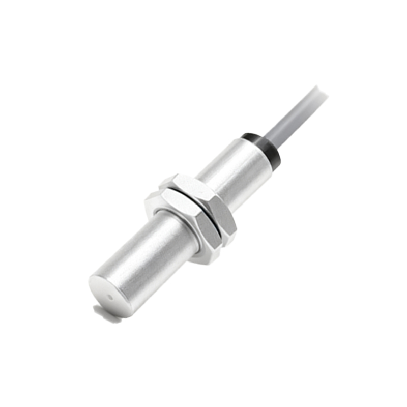
When selecting a DCF proximity sensor, several parameters require careful consideration. First is the sensing distance, or nominal range (Sn), which is typically shorter than equivalent standard inductive sensors for the same housing size. Engineers must account for this and ensure the target will come within this specified range. The housing material and style (e.g., cylindrical M8, M12, M18, or rectangular) must be chosen based on the mechanical constraints and environmental conditions (IP rating for dust and water resistance). The output configuration is critical: a 3-wire DC sensor with either a PNP (sourcing) or NPN (sinking) transistor output must be correctly matched to the PLC or control system input module. Operating voltage range (commonly 10-30V DC) and output current capacity are also key electrical specs. Lastly, connection methods, such as pre-wired cables or quick-disconnect connectors, influence maintenance and installation ease.
Installation and wiring follow standard practices for DC proximity sensors. Ensuring a stable DC power supply within the sensor's rated voltage is essential. The brown wire (typically) connects to DC+, the blue wire to DC-, and the black (or white) wire is the switched output signal. Proper grounding and routing of signal cables away from high-power lines are always recommended best practices, even with DCF's inherent noise immunity. Regular maintenance involves checking for physical damage, buildup of metallic debris on the sensing face, and verifying the switching signal under operational conditions.
In conclusion, DCF proximity switch sensors offer a specialized solution for challenging industrial environments where interference resistance and flush mounting in metal are required. Their operation based on a DC magnetic field provides distinct reliability advantages over conventional sensors when detecting ferromagnetic objects. For electrical engineers designing control systems for welding, heavy metalworking, or hydraulic applications, understanding and correctly applying DCF technology is key to achieving robust, fail-safe automation. As with any component, a careful review of the manufacturer's datasheet for specific model specifications is imperative for successful integration.