Magnetic proximity sensors are indispensable components in modern industrial automation, electrical control systems, and safety applications. As an electrical engineer, a deep understanding of their operating principles, types, selection criteria, and implementation nuances is crucial for designing robust and reliable systems. This guide delves into the core aspects of these sensors, providing a technical foundation for their effective application.
At its heart, a magnetic proximity sensor is a solid-state device that detects the presence or absence of a magnetic field, typically generated by a permanent magnet. Unlike inductive or capacitive sensors, they do not require physical contact with the target object (the magnet), making them ideal for harsh environments where dirt, oil, or moisture are present. The fundamental operating principle involves a sensing element, most commonly a reed switch or a Hall-effect integrated circuit.
Reed switch-based sensors contain two ferromagnetic, hermetically sealed reed contacts inside a glass tube filled with an inert gas. When an external magnetic field of sufficient strength is applied, the reeds magnetize, attract each other, and make contact, closing the circuit. When the magnet moves away, the reeds' spring force separates them, opening the circuit. These sensors are known for their simplicity, low cost, and ability to switch relatively high loads directly. However, they have limitations in switching speed, mechanical life (due to moving parts), and sensitivity to strong external magnetic fields.
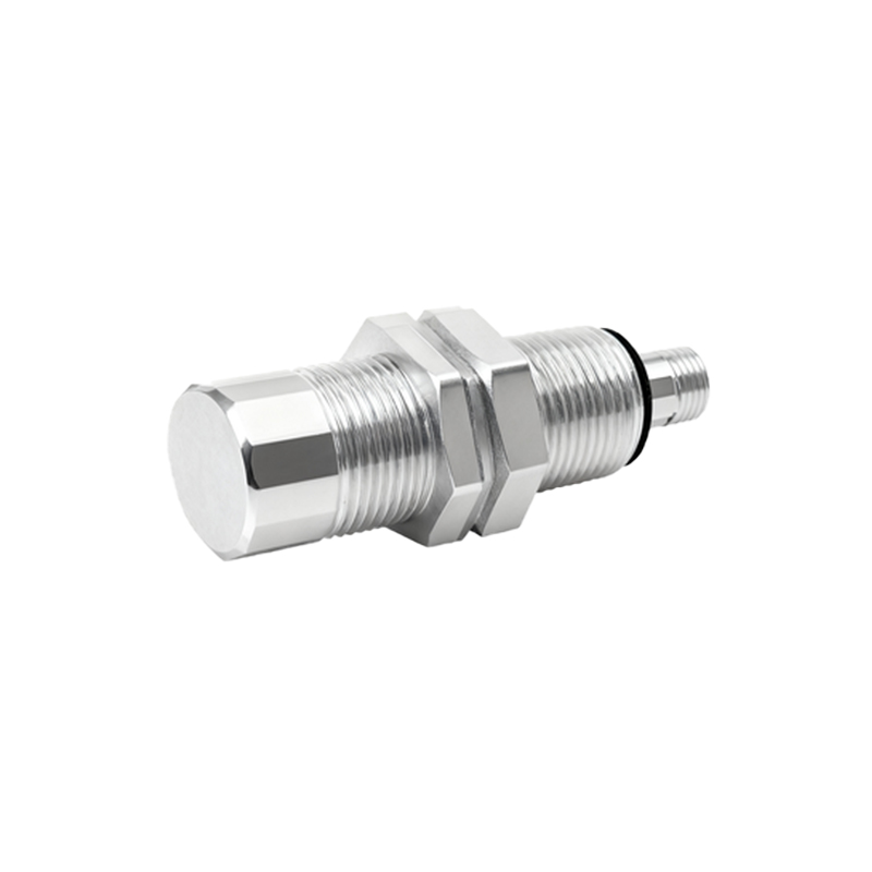
Hall-effect sensors represent a more advanced and widely used technology. They are based on the Hall effect, where a voltage difference (the Hall voltage) is generated across an electrical conductor when a magnetic field is applied perpendicular to the current flow. Modern Hall-effect sensors integrate this sensing element with signal conditioning, amplification, and switching circuitry into a single IC. They offer several advantages: no moving parts (infinite theoretical mechanical life), very high switching frequencies (up to several hundred kHz), precise switching points, and immunity to dust, dirt, and non-magnetic materials. They are typically categorized into two main types: unipolar (activated by a single south or north pole) and bipolar/latching (activated by one pole and deactivated by the opposite pole).
Key technical parameters for selection include:

1. Sensing Distance: The maximum nominal distance at which the sensor can reliably detect the standard magnet. This is typically conservative; actual maximum distance depends on magnet strength and size.
2. Output Type: Digital outputs include NPN (sinking), PNP (sourcing), and push-pull configurations. Analog outputs (voltage or current) provide a signal proportional to magnetic field strength. The choice depends on the PLC or controller input card.
3. Switching Function: Normally Open (NO), Normally Closed (NC), or changeover contacts.
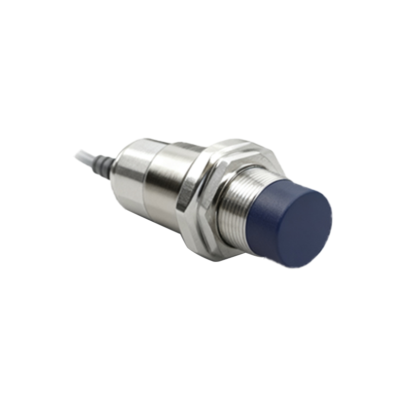
4. Supply Voltage: Common ranges are 5V DC, 10-30V DC, or 90-250V AC/DC for robust industrial models.
5. Housing and Protection Rating: Materials like PBT, stainless steel, and nickel-plated brass are common. Ingress Protection (IP) ratings (e.g., IP67, IP69K) and NEMA ratings define resistance to dust and water.
6. Temperature Range: Industrial sensors must operate reliably across a wide ambient temperature range, often from -25°C to +70°C or beyond.
In application, these sensors are ubiquitous. They are used for position detection (cylinder piston position in pneumatic/hydraulic systems, door/window open-close status), speed sensing (by counting gear teeth or rotor magnets), limit switching, and in safety interlocks. A critical design consideration is the selection and mounting of the actuating magnet. Factors like magnet material (e.g., Neodymium, Ferrite), size, shape, orientation (axial or diametric), and pole alignment significantly affect the achievable sensing distance and reliability. Shielding from stray magnetic fields from motors or transformers is also important to prevent false triggering.
Installation best practices involve ensuring proper alignment between the sensor and magnet, maintaining the specified air gap, and using non-magnetic mounting hardware (e.g., stainless steel screws of the correct grade). Electrical wiring must follow guidelines for cable length, shielding for noise immunity, and proper connection of the load and supply, including protective devices like flyback diodes for inductive loads.
In conclusion, magnetic proximity sensors offer a unique blend of reliability, environmental robustness, and versatility. For the electrical engineer, moving beyond a basic understanding to a mastery of Hall-effect technology, detailed datasheet parameters, and application-specific considerations is key. By correctly specifying and implementing these sensors, one can ensure enhanced system performance, reduced maintenance, and improved safety in a vast array of industrial and commercial applications. Their continued evolution, including miniaturization and integration of IO-Link and other smart communication protocols, ensures they will remain a cornerstone of sensing