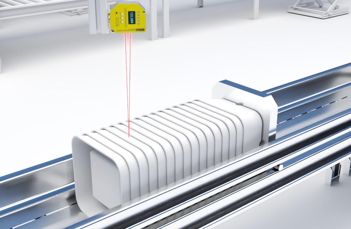
Laser proximity sensors are critical components in modern industrial automation, offering high-precision, non-contact detection for applications ranging from material handling to robotic guidance. However, like any sophisticated electronic device, they are susceptible to failures due to environmental factors, mechanical stress, or component degradation. As an experienced electrical engineer, I will guide you through a systematic approach to diagnosing and repairing common issues with laser proximity sensors, ensuring minimal downtime and cost-effective maintenance.
The first step in any repair process is accurate diagnosis. Begin by verifying the symptom: is the sensor failing to detect objects, providing inconsistent readings, or not powering on at all? Use a multimeter to check the power supply voltage at the sensor's terminals. Ensure it matches the sensor's specifications (commonly 10-30 VDC). If voltage is absent or unstable, trace back to the power source or wiring—loose connections, corroded terminals, or damaged cables are frequent culprits. Next, inspect the sensor's housing for physical damage, such as cracks or misalignment, which can affect the laser beam's path. Clean the lens carefully with a lint-free cloth and isopropyl alcohol, as dust, oil, or debris accumulation is a leading cause of reduced sensitivity or false triggers.
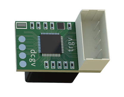
If basic checks don't resolve the issue, proceed to internal diagnostics. Power down the sensor and disassemble it according to the manufacturer's manual, typically involving removal of screws or clips. Inside, examine the printed circuit board (PCB) for visible signs of failure: burnt resistors, swollen capacitors, or charred traces. Use an oscilloscope to test the laser diode's output. A healthy diode should emit a stable, coherent beam when powered; erratic or dim output indicates diode failure, requiring replacement. Similarly, check the photodetector (often a phototransistor or photodiode) for responsiveness to light stimuli. Calibration adjustments might be necessary if the sensor's sensing distance has drifted—refer to the datasheet for potentiometer settings or software calibration procedures via serial communication.
For electronic repairs, component-level troubleshooting is essential. Common failures include voltage regulators, operational amplifiers, and signal conditioning ICs. Desolder and replace faulty components with exact equivalents, paying attention to ratings and tolerances. After repairs, reassemble the sensor securely, ensuring O-rings or gaskets are intact to maintain ingress protection (IP) ratings. Perform a functional test in a controlled environment: use calibration targets at known distances to verify detection consistency and repeatability. Document the repair process, including replaced parts and test results, for future reference and compliance with maintenance logs.
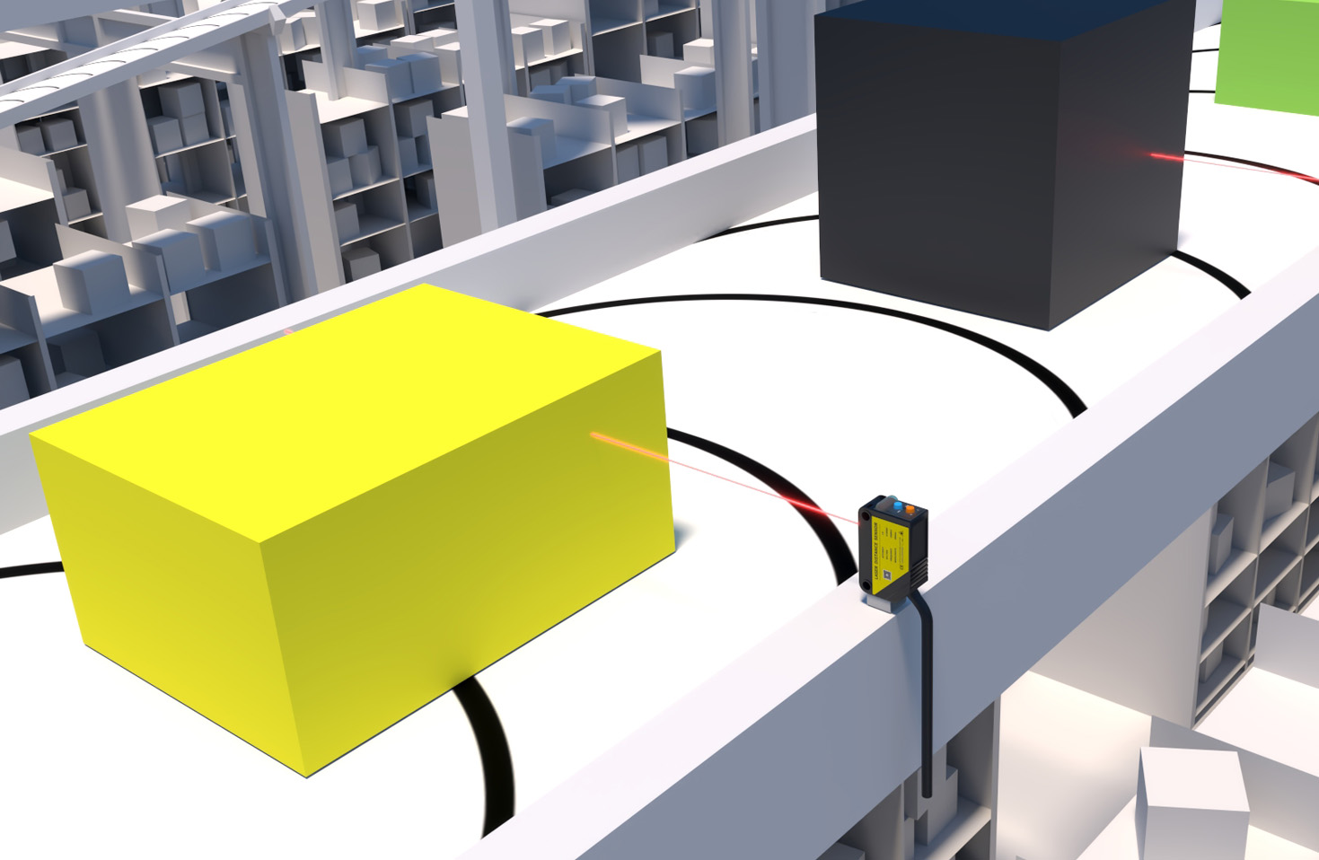
Preventive maintenance can extend sensor lifespan. Implement regular cleaning schedules, shield sensors from excessive vibration or temperature extremes, and use surge protectors in electrical lines. By mastering these repair techniques, engineers can enhance system reliability, reduce replacement costs, and contribute to efficient industrial operations. Remember, safety first: always disconnect power before servicing and follow electrostatic discharge (ESD) precautions when handling PCBs.