In the realm of industrial automation and electrical control systems, proximity sensors are indispensable components for non-contact detection of objects. Among the various wires in their connection cables, the brown wire holds a specific and critical function. This article delves into the role of the brown wire in standard proximity sensors, its wiring conventions, and essential considerations for proper installation and troubleshooting.
Standardized color coding for electrical wires is a fundamental practice that enhances safety, simplifies installation, and ensures global consistency. For DC (Direct Current) proximity sensors, which are the most common type, the international standard IEC 60947-5-2 typically defines the following color scheme:
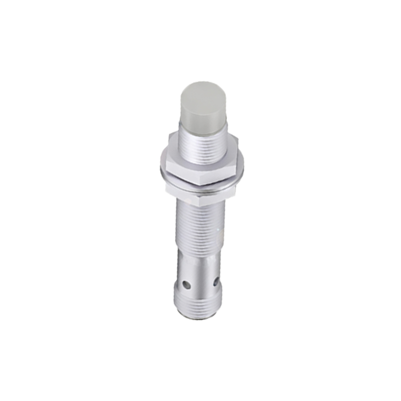
Brown Wire: This is universally designated as the positive supply voltage line (+V or +Vs).
Blue Wire: This is universally designated as the negative supply voltage line (0V or Common).
Black Wire: This is the output signal line. In a sinking (NPN) sensor, the black wire switches the load to 0V. In a sourcing (PNP) sensor, it switches the load to +V.
White Wire: Often used as a second output or a complementary signal, depending on the sensor model.
Therefore, the primary and unequivocal function of the brown wire is to carry the positive DC supply voltage to the sensor. It is the lifeline that powers the sensor's internal oscillator, amplifier, and switching circuitry. Without a proper connection to the brown wire, the sensor will not activate, regardless of the state of other connections.
Wiring Practices and Circuit Configuration:
Correct wiring is paramount for reliable operation. The standard connection for a 3-wire DC proximity sensor is as follows:
1. Connect the brown wire to the positive terminal of your DC power supply (e.g., +24VDC).
2. Connect the blue wire to the negative terminal (0VDC) of the same power supply.
3. Connect the black wire (output) to your load (e.g., a PLC input, relay coil, or indicator lamp).
4. The other terminal of the load must then be connected to complete the circuit. The connection point depends on the sensor type:
For a PNP (sourcing) sensor, the load's other terminal is connected to the power supply's 0V (blue wire line).
For an NPN (sinking) sensor, the load's other terminal is connected to the power supply's +V (brown wire line).
It is absolutely critical to verify the sensor's type (PNP or NPN) and the required supply voltage (commonly 10-30VDC) before wiring. Applying power incorrectly, such as connecting the brown wire to a negative potential, can cause permanent damage to the sensor.
Safety and Troubleshooting Insights:
Always de-energize the circuit before making any connections or modifications. Use appropriate wire gauges capable of handling the sensor's current consumption and the inrush currents of the connected load. Secure connections with proper terminals to prevent loose wires, which are a common source of intermittent failures.
When a proximity sensor fails to operate, a systematic check of the brown wire's connection is the first logical step. Use a multimeter to confirm that:
Voltage is present between the brown and blue wires at the sensor's cable end (matching the sensor's rated voltage).
The polarity is correct (brown is positive relative to blue).
There are no breaks or high resistance in the brown wire run.
In some specialized or older sensors, or those from specific manufacturers, color codes might deviate. A white wire might sometimes be used for a normally closed (NC) output. However, the brown/blue/black scheme for +V/0V/Output is so prevalent that any deviation should be clearly marked on the sensor's housing or in its datasheet. Never assume wire function based solely on color if the standard is in doubt; always consult the manufacturer's documentation.
Understanding the simple yet vital role of the brown wire—the positive supply conductor—is foundational for anyone working with industrial sensors. Adherence to wiring standards and careful attention to polarity and sensor type will ensure robust, reliable performance in automated systems, minimizing downtime and maintaining operational efficiency.