In modern industrial automation, laser sensors play a crucial role in precision measurement, object detection, and quality control. Properly connecting a laser sensor assembly line is essential for ensuring reliable operation, minimizing downtime, and maintaining high productivity. This guide provides a step-by-step approach to wiring and integrating laser sensors into an assembly line, covering electrical connections, communication protocols, and safety considerations.
First, understand the specifications of your laser sensor. Most industrial laser sensors operate on DC voltage, typically 12-24V DC, and have outputs such as NPN, PNP, or analog signals. Check the datasheet for voltage requirements, output types, and load capacity. Ensure the power supply matches the sensor's input range to prevent damage. Use shielded cables to reduce electrical noise interference, especially in environments with motors or frequency drives.
Begin by connecting the power supply. For a 24V DC sensor, connect the positive terminal to the sensor's V+ or brown wire, and the negative terminal to the 0V or blue wire. Ground the sensor's housing or shield wire to the earth ground to enhance safety and stability. If using multiple sensors, consider a centralized power distribution unit to avoid voltage drops.
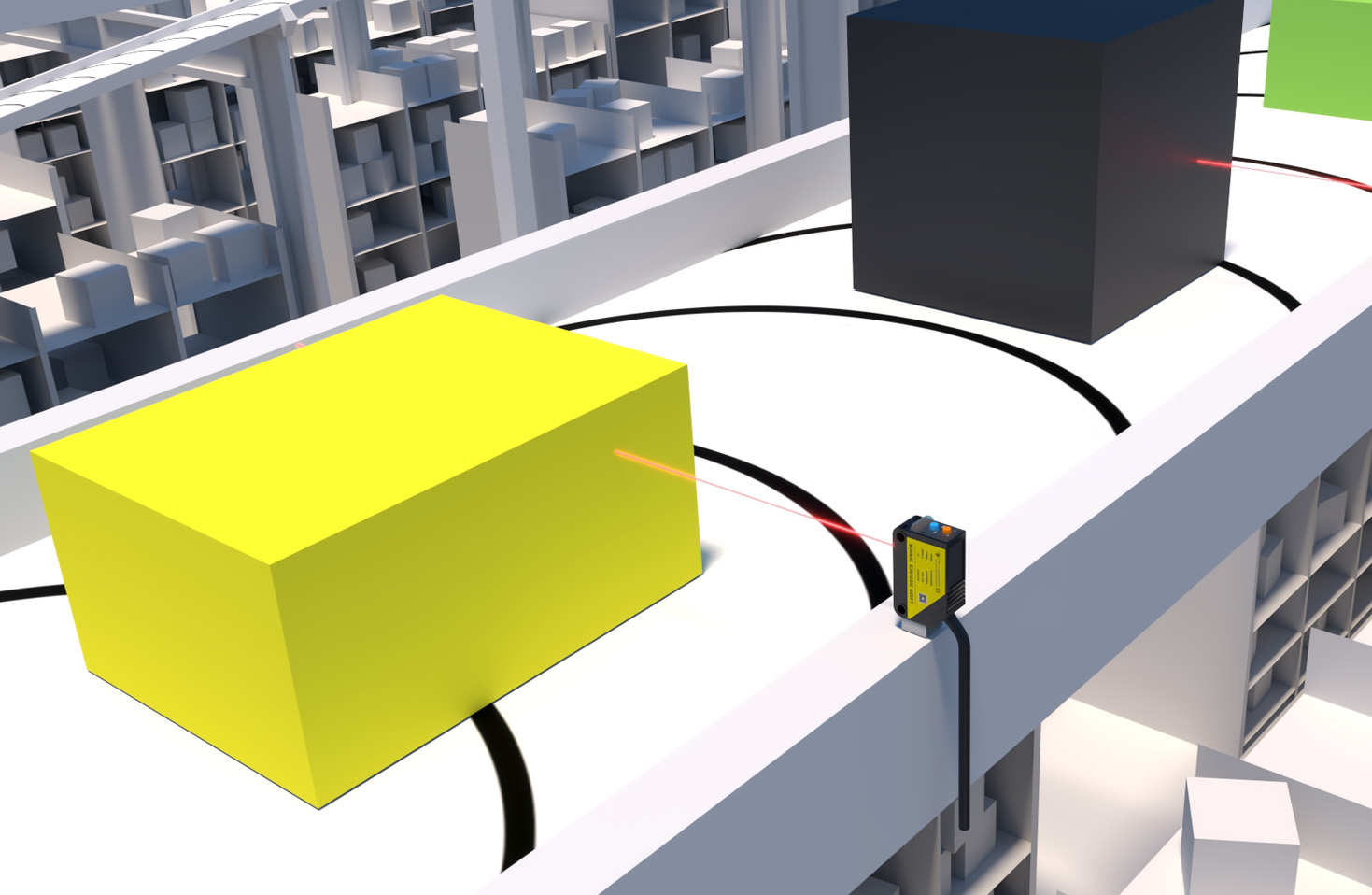
Next, wire the output signals. For digital outputs (e.g., NPN or PNP), connect the output wire (usually black or white) to the controller input, such as a PLC (Programmable Logic Controller). NPN sensors sink current to ground, while PNP sensors source current from positive voltage. Ensure compatibility with your PLC's input module. For analog outputs (e.g., 0-10V or 4-20mA), connect the signal wire to the analog input module, and use twisted-pair cables to minimize signal degradation.
Communication integration is key for advanced assembly lines. Many laser sensors support protocols like IO-Link, PROFINET, or EtherNet/IP. To connect via IO-Link, use a 3-wire cable (power, ground, and data) and an IO-Link master module. Configure the sensor parameters through software, such as setting measurement ranges or output modes. For network protocols, connect the sensor to an industrial switch via Ethernet cable and assign an IP address. Use configuration tools to map data to the control system for real-time monitoring.
Safety precautions are paramount. Always disconnect power before wiring to prevent electric shock. Follow local electrical codes and use proper insulation. Implement emergency stop circuits and protective enclosures if the laser is Class 2 or higher. Regularly inspect connections for wear or corrosion, and test the sensor's alignment and calibration to ensure accurate performance.
In summary, connecting a laser sensor assembly line involves careful planning of power, signals, and communication. By adhering to manufacturer guidelines and industry standards, you can achieve a robust and efficient automation setup. This process not only enhances operational reliability but also supports scalable and smart manufacturing initiatives.
