In the complex and often electrically noisy landscape of modern industrial automation, proximity sensors are indispensable workhorses. These non-contact devices reliably detect the presence or absence of metallic or non-metallic objects, forming the backbone of countless processes from positioning and counting to safety interlocks. However, their very sensitivity makes them susceptible to electromagnetic interference (EMI), which can lead to erratic behavior, false triggering, or complete operational failure. Proper shielding is not merely an enhancement; it is a critical requirement for ensuring signal integrity, system reliability, and longevity. This article delves into the principles and practical methodologies for effectively shielding proximity sensors.
The primary sources of interference for proximity sensors are typically categorized into three types: radiated EMI, conducted EMI, and crosstalk. Radiated EMI originates from sources like variable frequency drives (VFDs), welding equipment, radio transmitters, and even other high-current switching devices. This interference is transmitted through the air and can be picked up by the sensor's housing or, more critically, its cabling. Conducted EMI travels along power supply lines or shared ground paths, often introduced by the same noisy equipment. Crosstalk occurs when signals from one cable induce unwanted voltages in an adjacent cable, especially problematic when sensor cables are routed in parallel with motor power cables over long distances.
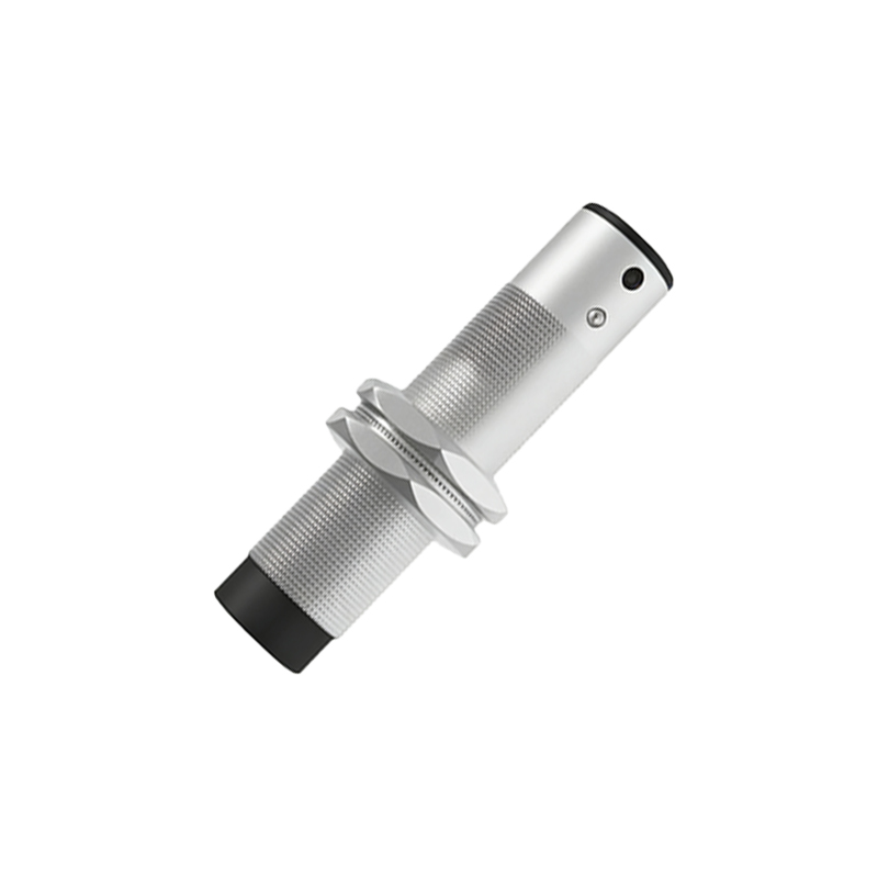
Effective shielding strategies must address these pathways comprehensively. The first line of defense is the sensor's own design. Many high-quality inductive and capacitive proximity sensors feature an integrated metal housing or a shielded face that provides a degree of inherent protection against radiated interference from the front and sides. It is crucial to select sensors rated appropriately for the electromagnetic environment, often indicated by standards like IEC 60947-5-2, which specifies performance criteria for proximity devices in industrial settings.
The most significant vulnerability, however, lies in the cabling. Unshielded cables act as efficient antennas, broadcasting and receiving EMI. Therefore, the use of shielded cable is non-negotiable in environments with significant electrical noise. A proper shielded cable consists of insulated conductors surrounded by a metallic shield, typically a braided copper mesh or a conductive foil. This shield functions as a Faraday cage, diverting induced interference currents away from the internal signal conductors and providing a low-impedance path to ground.
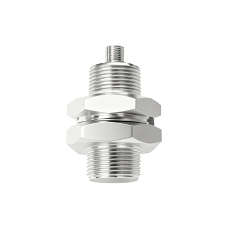
Correct installation of the cable shield is paramount. A shield that is not properly terminated is virtually useless. The golden rule is to ground the shield at one end only, typically at the control system or PLC cabinet end. Grounding at both ends can create ground loops—circular paths where differences in ground potential between two points can drive currents through the shield itself, which can then induce new interference into the signal wires. The ground connection must be made to a clean, stable earth ground point using a dedicated grounding terminal or clamp, ensuring a large surface area contact. The shield should be connected directly to the grounding terminal before the cable enters the cabinet, avoiding "pigtail" connections, which increase high-frequency impedance and reduce shielding effectiveness. For optimal performance, use connectors that maintain 360-degree circumferential contact with the shield.
Physical routing is another critical factor. Always separate sensor signal cables from power cables. Follow industry best practices: maintain a minimum separation of 12 inches (300 mm) when running parallel. If cables must cross, they should do so at a 90-degree angle to minimize the area of inductive coupling. Route cables in dedicated cable trays or conduits; using metal conduits can provide additional shielding if they are properly grounded. Avoid running sensor cables near known strong sources of EMI, such as transformers or large motors.
For sensors with analog outputs (e.g., 4-20mA, 0-10V), which are even more susceptible to noise, additional precautions are necessary. Twisted-pair shielded cable is highly recommended for analog signals, as the twisting helps cancel out magnetically induced interference. In extreme cases, or for very long cable runs, the use of signal isolators or conditioners can be invaluable. These devices electrically isolate the sensor circuit from the control system, breaking ground loops and providing a clean, regenerated output signal.
Conducted interference on power lines can be mitigated by using filtered power supplies or installing ferrite cores. Clip-on ferrite chokes placed on the cable near the sensor or the controller can attenuate high-frequency noise. For systems powered by DC, ensuring a stable, well-regulated power supply with sufficient filtering capacitance is essential.
Finally, a systematic approach to troubleshooting is vital. If a previously stable sensor begins to malfunction, investigate recent changes in the electrical environment. Use diagnostic tools like an oscilloscope to visualize noise on the signal line. Verify all grounding connections for integrity and low resistance. Remember that shielding is a system-wide endeavor; a single unshielded segment or poor connection can compromise the entire setup.
In conclusion, shielding proximity sensors is a multifaceted engineering task that integrates