Proximity sensors are essential components in modern industrial automation, enabling non-contact detection of objects. Understanding how to properly install, wire, and configure these sensors is critical for ensuring reliable operation in applications ranging from assembly lines to safety systems. This guide provides a clear, diagram-supported walkthrough for using inductive, capacitive, and magnetic proximity sensors effectively.
Step 1: Selecting the Right Proximity Sensor
Before installation, identify the sensor type based on your application. Inductive sensors detect metallic objects and are ideal for machinery positioning. Capacitive sensors can sense both metallic and non-metallic materials, such as plastics or liquids, making them suitable for level detection. Magnetic sensors (e.g., reed switches) are used for detecting magnetic fields, often in hydraulic cylinders. Refer to the manufacturer’s datasheet for specifications like sensing range, output type (PNP/NPN), and voltage rating (commonly 10-30V DC).
Step 2: Mounting the Sensor
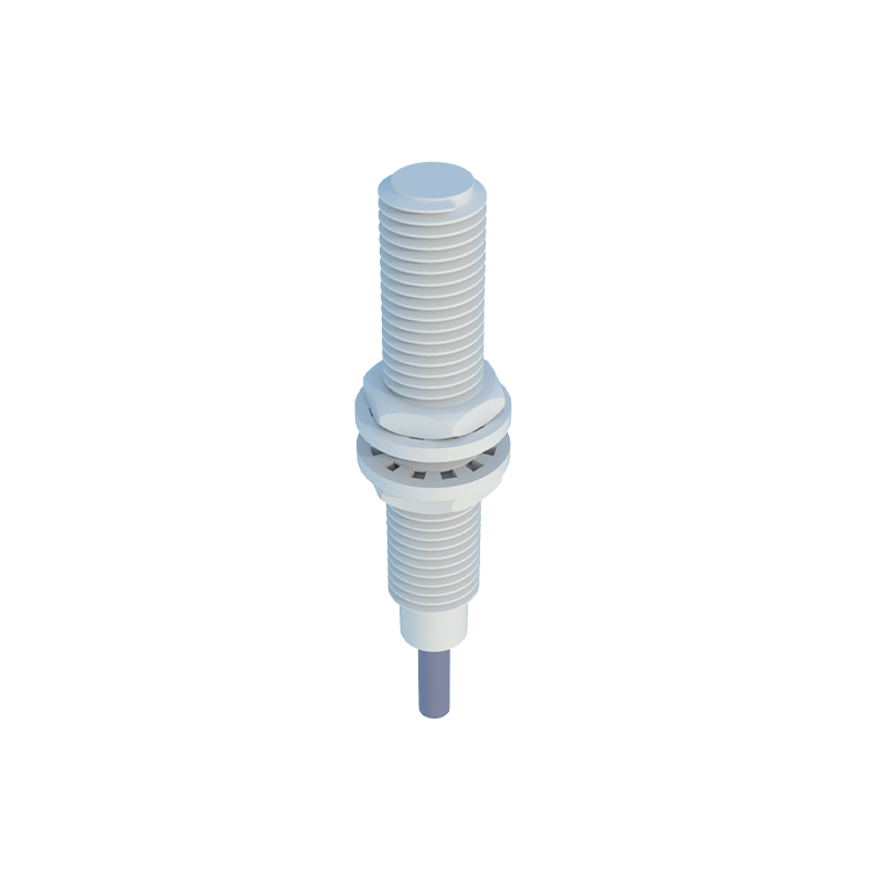
Proper mounting ensures accurate detection. For inductive and capacitive sensors, maintain a clearance around the sensing face to avoid interference from surrounding metal or materials. As shown in Diagram 1, mount the sensor perpendicular to the target object, ensuring the target enters within the specified sensing distance. Use brackets or threaded housings for secure fixation, and avoid overtightening to prevent housing damage. For cylindrical sensors, typical mounting involves embedding them in a drilled hole with adequate lateral space.
Step 3: Wiring Connections
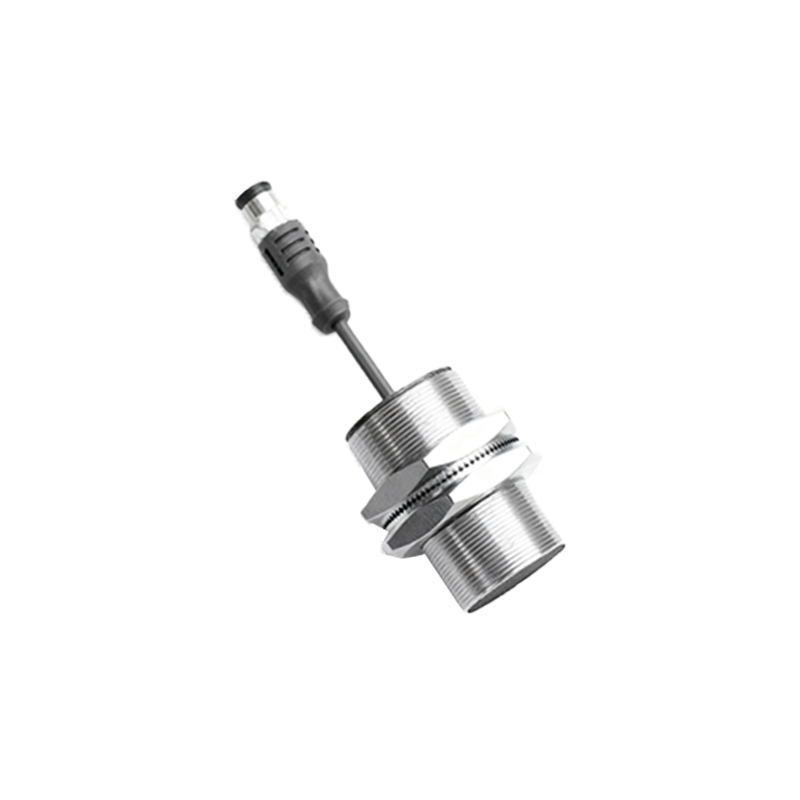
Wiring diagrams vary by sensor output. Most proximity sensors have three wires: brown (power+), blue (power-), and black (output signal). For a PNP sensor (sourcing output), connect brown to DC+, blue to DC-, and black to the load (e.g., PLC input). For an NPN sensor (sinking output), the black wire connects to DC- through the load. Diagram 2 illustrates both configurations. Always disconnect power during wiring to prevent short circuits. Shield cables in high-noise environments and ensure grounding for capacitive sensors to reduce false triggers.
Step 4: Adjusting Sensitivity and Range
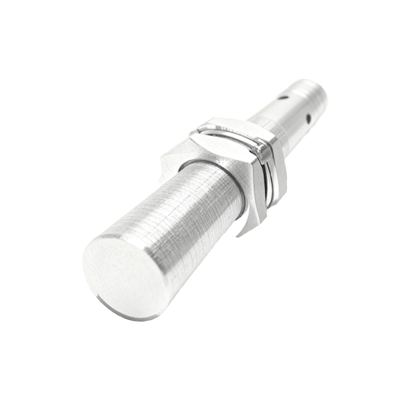
Some sensors feature potentiometers for sensitivity adjustment. For capacitive sensors, turn the potentiometer clockwise to increase sensitivity for detecting lighter materials, but avoid over-adjustment to prevent sensing unintended objects. Inductive sensors typically have fixed ranges, so ensure the target object size meets the sensor’s specifications (e.g., standard sensing distances range from 2mm to 20mm). Use a test object to verify detection consistency, as shown in Diagram 3, where a metal plate is moved toward the sensor face until the output LED activates.
Step 5: Testing and Troubleshooting
After installation, power the system and observe the sensor’s indicator LED. When a target object enters the sensing zone, the LED should illuminate, signaling output activation. If the sensor fails to detect, check: power supply voltage, wiring polarity, target material compatibility, and environmental factors like dust or moisture. Diagram 4 demonstrates a testing setup with a multimeter to measure output voltage. For intermittent operation, reduce electrical noise by separating sensor cables from high-voltage lines or using ferrite cores.
Step 6: Integration with Control Systems
Connect the sensor output to a PLC, relay, or microcontroller. Ensure the load current does not exceed the sensor’s rating (usually below 200mA). In PLC applications, program the input to trigger actions like stopping a conveyor or counting items. Diagram 5 shows a ladder logic example where a proximity sensor input activates a motor coil. For repetitive tasks, consider sensors with teach-in functions for automatic calibration.
By following these steps and referring to the diagrams, users can deploy proximity sensors efficiently. Regular maintenance, such as cleaning sensing faces and checking connections, prolongs sensor life. Always consult specific product manuals for detailed instructions, as designs may vary by brand and model.