In the realm of precision measurement and industrial automation, laser displacement sensors are indispensable tools for non-contact distance and position detection. A common point of confusion among engineers and technicians, however, revolves around the interpretation of negative values in sensor readings. This article delves into the operational principles behind these negative readings, their practical implications, and best practices for handling them in various industrial applications.
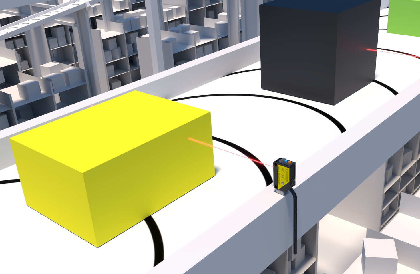
At its core, a laser displacement sensor operates by projecting a laser beam onto a target surface and analyzing the reflected light, typically using triangulation or time-of-flight principles. The sensor's internal processor calculates the distance to the target and outputs this as a value relative to a predefined reference position, often called the reference plane or zero point.

The emergence of a negative value is fundamentally a matter of coordinate system definition. The sensor's output is not an absolute physical distance but a displacement relative to this established zero point. When the target surface is positioned behind this reference plane (from the sensor's perspective), the measured displacement is reported as a negative value. Conversely, a target in front of the reference plane yields a positive value. This is analogous to a graph where the zero point is the origin; points on one side are positive, and points on the other are negative.
Several key factors can lead to negative readings:
1. Intentional Setup: Often, the reference plane is set at a specific feature, such as the nominal surface of a part. Variations in part thickness or mounting position will then show as positive or negative deviations, which is critical for quality control (e.g., measuring warpage or concavity).
2. Target Movement: In dynamic applications like vibration analysis or runout measurement, a moving target will naturally oscillate around a mean position, generating both positive and negative values.
3. Environmental Effects: Thermal expansion of the sensor mount, the target, or the machine structure can subtly shift the effective distance, potentially causing readings to drift from positive into negative territory.
4. Electrical Noise or Interference: While less common, signal interference can sometimes corrupt the output signal, leading to erroneous negative spikes. Proper shielding and grounding are essential mitigations.
From an application standpoint, negative values are not inherently indicative of an error. They are rich with information:
* Dimensional Tolerance Checking: They directly show if a feature is above or below the nominal specification.
* Profile and Flatness Measurement: Scanning a surface produces a profile where negative values indicate valleys or recesses.
* Gap and Clearance Measurement: When measuring the gap between two components, setting the zero point on one component's surface will show the other component's position as positive or negative, clearly indicating the gap width and alignment.
To effectively manage and utilize negative values, consider the following engineering practices:
* Clear Definition: Explicitly define the physical meaning of the zero point in your system documentation. Is it the surface of a fixture, a master part, or a theoretical plane?
* Sensor Configuration: Most modern sensors allow you to set the output range and preset value. You can offset the output so that the operational range falls entirely within positive numbers if required by the receiving controller (e.g., a PLC that only accepts 4-20mA signals for positive ranges). However, retaining the signed data often provides more flexibility for data analysis.
* Data Processing: Implement software filters or logic in your SCADA or data acquisition system to interpret the signed data correctly. Set alarms for values that exceed negative or positive tolerance bands.
* Regular Calibration: Periodically verify the sensor's zero point against a physical standard to ensure long-term measurement integrity and prevent drift-related inaccuracies.
In conclusion, negative values from a laser displacement sensor are a normal and functional aspect of its operation, representing displacement in a defined direction from a reference. Rather than being viewed as a problem, they should be understood as a crucial feature that enables bidirectional measurement and high-precision deviation analysis. A proper grasp of the sensor's coordinate setup, combined with robust system integration practices, allows engineers to fully leverage this capability for enhanced process control, quality assurance, and diagnostic insight in demanding industrial environments. The key is to master the frame of reference, and the data—positive or negative—becomes powerfully meaningful.