In modern industrial automation and control systems, green proximity sensors have become indispensable components for non-contact object detection. Their reliability, durability, and energy-efficient operation make them a preferred choice in various applications, from packaging machinery to robotic assembly lines. Unlike their traditional counterparts, many modern "green" sensors emphasize energy efficiency and often feature LED status indicators, but their core wiring principles remain grounded in standard industrial practices. This guide provides a detailed, professional overview of how to correctly wire a 3-wire DC green proximity sensor, which is the most common configuration encountered in the field.
Before beginning any wiring procedure, the paramount rule is safety. Always ensure that all power sources to the control panel and the machine are locked out and tagged out (LOTO). Verify the absence of voltage using a appropriately rated multimeter. Carefully review the sensor's datasheet. Critical specifications include the sensing type (PNP or NPN), operating voltage range (commonly 10-30V DC), output type (normally open (NO) or normally closed (NC)), and current rating. Misidentifying these can lead to sensor failure or damage to the controller.
A standard 3-wire DC proximity sensor has three distinct wires, typically color-coded as follows: Brown, Blue, and Black. However, always confirm this with the manufacturer's documentation, as colors can vary. The brown wire is universally the positive supply line (+V). The blue wire is the common negative or 0V line. The black wire is the switched output signal line. The core difference lies in whether the sensor is a PNP (sourcing) or NPN (sinking) type, which determines how the black output wire functions in the circuit.
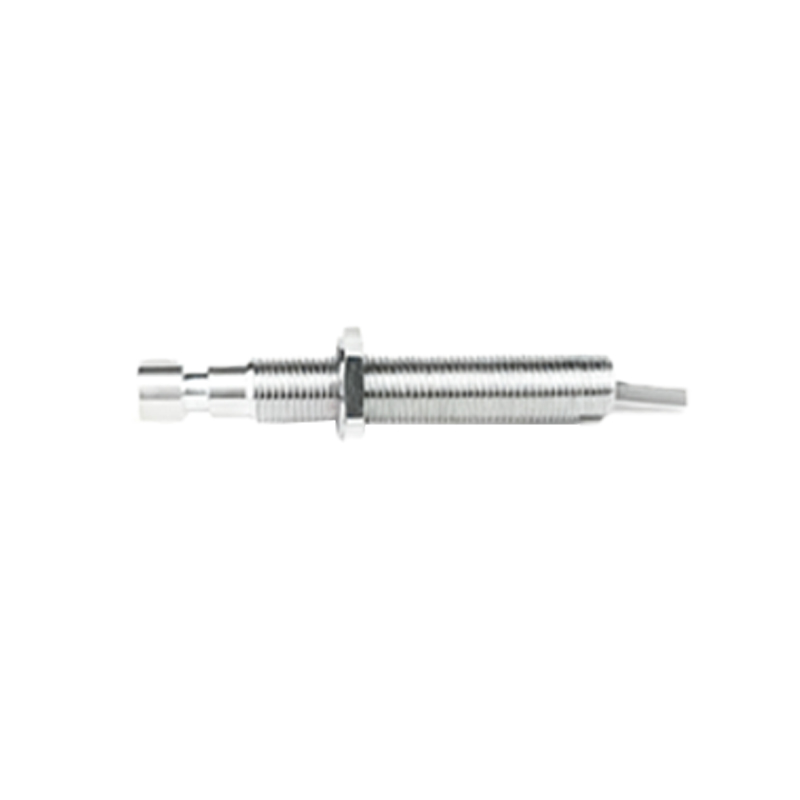
For a PNP sensor, the black wire sources current. When the sensor detects a target, it switches the black output wire to connect internally to the positive supply (brown wire). This means the output becomes "high" (e.g., +24V) relative to the common blue wire. To complete the circuit, the load (e.g., a PLC input module, relay coil, or indicator lamp) is connected between the black output wire and the common negative (blue wire). When the sensor activates, current flows from the sensor's black wire, through the load, and to the blue wire.
For an NPN sensor, the black wire sinks current. When activated, it switches the black output wire to connect internally to the negative supply (blue wire). The output becomes "low" (0V). Here, the load must be connected between the positive supply (brown wire) and the black output wire. Current flows from the positive supply, through the load, and into the sensor's black wire, which then sinks it to negative.
The wiring steps are systematic. First, run the cables from the sensor to the control cabinet through a suitable conduit for protection. Inside the cabinet, strip the wire ends appropriately. Connect the sensor's brown wire to the positive DC supply terminal (e.g., +24V). Connect the sensor's blue wire to the DC common or 0V terminal. For the critical output connection: If using a PNP sensor, connect one side of your load to the sensor's black wire. Connect the other side of the load to the 0V (blue wire) terminal. If using an NPN sensor, connect one side of your load to the +24V supply. Connect the other side of the load to the sensor's black wire.
After connections are made and double-checked, apply power. Most green proximity sensors have an LED indicator that will illuminate steadily when powered and may blink or change state when a target is detected. Use a multimeter to verify the voltage on the black wire relative to the blue wire. For a PNP sensor, it should read near 0V when idle and near the supply voltage (e.g., 24V) when activated. For an NPN, it should read near the supply voltage when idle and near 0V when activated.
Troubleshooting is a key skill. If the sensor LED does not light, check power and ground connections. If the LED is on but there is no output signal, verify the target is within the sensing range and is of the correct material (ferrous/non-ferrous for inductive sensors). Ensure the load's current draw does not exceed the sensor's rated capacity. Incorrect PNP/NPN selection for the PLC input type is a very common issue; a PNP sensor cannot directly drive an NPN-configured input, and vice-versa.
Finally, consider best practices. Always use fuses or circuit breakers for protection. Implement proper shielding and separation from high-voltage AC lines to prevent electrical noise interference. Secure all connections