In the realm of industrial automation, proximity sensors are indispensable components, providing non-contact detection of metallic or non-metallic objects. However, their reliable operation is frequently compromised by electromagnetic interference (EMI), electrical noise, and physical environmental factors. Shielding these sensors is not merely an optional enhancement but a critical engineering practice to ensure signal integrity, accuracy, and system longevity. This article delves into the core principles and practical methodologies for effectively shielding proximity sensors.
The primary threat to an unshielded proximity sensor is electromagnetic interference, which originates from various sources within industrial settings. Common culprits include variable frequency drives (VFDs), welding equipment, large motors, and power lines. These sources generate intense electromagnetic fields that can induce erroneous signals in the sensor's circuitry, leading to false triggering or failure to detect. Furthermore, capacitive coupling between sensor cables and nearby power cables can introduce significant noise. Physical threats, such as metal chips, conductive dust, or moisture, can also cause malfunction by creating unintended conductive paths or short circuits.
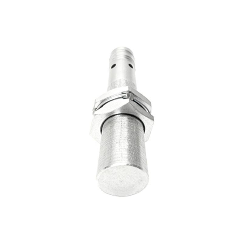
Effective shielding strategies must address both electromagnetic and physical protection. The first line of defense is the sensor's own housing. Many industrial-grade inductive and capacitive proximity sensors are manufactured with integrated metal housings, typically from stainless steel or brass, which act as a Faraday cage. This metallic enclosure attenuates external electric fields. For optimal performance, this housing must be properly grounded. A low-impedance ground connection provides a path for interference currents to safely dissipate into the earth, preventing them from affecting the internal sensing electronics.
Cable shielding is equally paramount. Sensor cables should be equipped with a braided or foil shield, often made of tinned copper. This shield must be connected to ground at only one end, typically at the controller or PLC cabinet, to prevent ground loops. Ground loops occur when multiple ground points create a potential difference, causing current to flow through the shield itself, which then becomes a source of noise. The use of twisted-pair wiring within the cable further enhances noise immunity by ensuring that induced interference affects both conductors equally, allowing the differential input of the amplifier to cancel it out.
Installation practices profoundly impact shielding effectiveness. A fundamental rule is to maintain physical separation between sensor cables and power cables. Running them in parallel, especially over long distances, guarantees capacitive and inductive coupling. Where possible, sensor cables should be routed through dedicated metallic conduits or cable trays, which provide additional shielding. If cables must cross, they should do so at a 90-degree angle to minimize the area of interaction. Securing cable shields properly at connection points using appropriate cable glands or shield clamps is essential to maintain continuity.
In environments with extreme EMI, such as near arc furnaces or high-power radio transmitters, additional measures are necessary. Ferrite cores or beads can be clamped onto the sensor cable near the connection point. These components suppress high-frequency noise by presenting high impedance to common-mode interference. For sensors with analog outputs (e.g., 4-20mA or 0-10V), using signal conditioners or isolators can break ground loops and provide a clean, amplified signal to the control system. These devices often include built-in filtering for additional noise rejection.
Environmental sealing, while distinct from EMI shielding, is a complementary aspect of protection. Sensors rated with high Ingress Protection (IP) codes (e.g., IP67, IP69K) are sealed against dust and water ingress. This prevents conductive contaminants from bridging connections or settling on the sensor face, which could alter its sensing characteristics. For sensors in washdown or corrosive environments, choosing housings made of materials like PPS or PVDF is advisable.
Regular maintenance and verification form the final pillar of a robust shielding strategy. Periodic inspections should check for shield integrity, corrosion at grounding points, and physical damage to cables or conduits. Using an oscilloscope to monitor the sensor's signal line for noise spikes can identify developing interference issues before they cause production downtime. Implementing a predictive maintenance schedule that includes these checks ensures long-term reliability.
In conclusion, shielding proximity sensors is a multifaceted engineering challenge requiring a holistic approach. It encompasses proper product selection with integrated shielding, meticulous attention to cable management and grounding, strategic use of supplemental filtering, and adherence to rigorous installation standards. By systematically addressing both electromagnetic and environmental threats, engineers can create automation systems where proximity sensors perform with unwavering precision, thereby maximizing uptime and productivity in demanding industrial applications.