In industrial automation and control systems, proximity sensors play a critical role in detecting the presence or absence of objects without physical contact. As an experienced electrical engineer, I often encounter questions about how to effectively judge whether a proximity sensor is functioning properly or has deteriorated. This guide outlines practical, field-tested methods to assess sensor health, ensuring system reliability and minimizing downtime.
First, understand the basic types: inductive sensors detect metallic objects, capacitive sensors handle both metallic and non-metallic materials, and ultrasonic or photoelectric sensors use sound or light waves. Knowing your sensor type is essential, as testing methods vary.
Start with a visual inspection. Check for physical damage such as cracks, dents, or corrosion on the housing and sensing face. Ensure the connector and cable are intact, without cuts, fraying, or loose connections. Environmental factors like moisture, dust, or chemical exposure can degrade sensors over time, so examine for signs of contamination or wear.
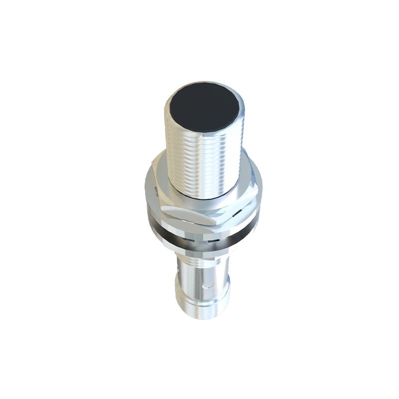
Next, verify electrical characteristics using a multimeter. For DC sensors, measure the output voltage in both triggered and non-triggered states. In the non-triggered state, the output should be near the supply voltage (for PNP types) or near 0V (for NPN types). When an appropriate target enters the sensing range, the voltage should switch accordingly. Anomalies like fluctuating readings or failure to switch indicate potential internal circuit issues. For AC sensors, use an AC voltage setting and check for proper switching; also, measure current draw to ensure it aligns with datasheet specifications—excessive current may signal internal shorts.
Assess sensing performance by testing the actual sensing distance. Place a standard target (specified in the datasheet, typically a square iron plate for inductive sensors) at the rated sensing distance. The sensor should reliably detect the target. Gradually move the target closer and farther to verify the operating point and release point, ensuring hysteresis is within normal range. A significant reduction in effective sensing range often points to aging components or weakened oscillator circuits in inductive sensors.
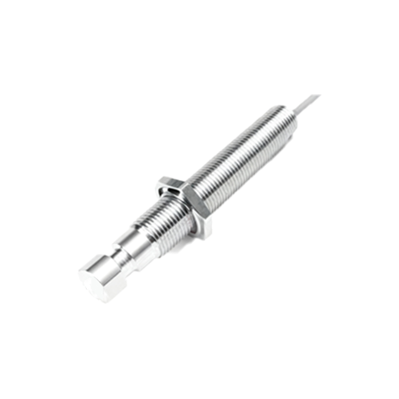
Monitor output behavior with an oscilloscope if available. This reveals switching speed, signal integrity, and noise. Look for clean, sharp transitions without excessive ringing or delay. Noisy or sluggish switching can cause false triggers or missed detections in high-speed applications. For analog output sensors, verify the output curve is linear and matches the expected response across the sensing range.
Evaluate environmental immunity. Proximity sensors can be affected by electromagnetic interference (EMI), temperature extremes, or vibration. Test operation under normal conditions and then introduce potential interferers—like nearby motors, transformers, or variable frequency drives—to see if false triggering occurs. Temperature testing can be done by gently heating or cooling the sensor (within its rated limits) while monitoring performance; drift beyond specifications suggests thermal compensation issues.
Utilize diagnostic features if present. Many modern sensors include LED indicators for power, output status, and diagnostics. A steady or blinking LED pattern can indicate specific faults (e.g., short-circuit, overload, or alignment errors). Refer to the manufacturer’s manual for code interpretations. Additionally, some smart sensors offer IO-Link or other digital communication, allowing parameter readback and health monitoring via software.
Compare against known good units or datasheet benchmarks. Keep a reference sensor for critical applications. Document baseline performance metrics during installation, such as response time, sensing consistency, and output voltage levels. Periodic re-testing against these baselines helps identify gradual degradation before failure.
Common failure modes include output stuck high/low, reduced sensing distance, intermittent operation, or overheating. Causes range from internal component failure (e.g., damaged oscillator, output transistor) to external issues like wiring faults, incorrect load, or power supply problems. Always rule out external factors before condemning the sensor.
In summary, a systematic approach combining visual checks, electrical measurements, functional testing, and environmental validation provides a reliable assessment of proximity sensor condition. Regular preventive maintenance based on these methods enhances operational safety and efficiency. Remember, when in doubt, consult the sensor’s datasheet and manufacturer guidelines, as specifications and testing procedures can vary by model and technology.