In the realm of industrial automation and machine design, proximity sensors are indispensable components for non-contact detection. A critical, yet sometimes overlooked, aspect of their installation and integration is the sensor jack or connector interface. This guide delves into the specifics of proximity sensor jack images, explaining their significance, common types, and key visual identifiers to aid engineers in selection, troubleshooting, and documentation.
A proximity sensor jack image is more than just a photograph; it is a vital piece of technical data. It provides immediate visual confirmation of the connector type, pin configuration, housing material, and keying features. For engineers reviewing datasheets, creating bills of materials, or diagnosing field issues, a clear, high-resolution image can prevent costly mismatches and installation errors. The jack is the physical gateway for power, signal output, and often diagnostic communication, making its compatibility with the mating cable or socket paramount.
Several standard connector types dominate the proximity sensor landscape, each with distinct visual characteristics visible in a proper image. The ubiquitous M8 and M12 circular connectors are perhaps the most common. An image of an M12 jack, for instance, will typically show a 4-pin or 3-pin configuration (though 5-pin and 6-pin exist for specialized functions). The metal threaded barrel and the specific arrangement of pins within the insulating insert are clear markers. M8 jacks appear similar but are noticeably smaller in diameter. Close-up images should reveal the thread pitch and the presence of a locking notch or a specific coding rib to prevent incorrect mating, a feature especially important in IP67 or IP69K rated sensors where environmental sealing is critical.
Another frequent type is the rectangular or mini-style connector, often used in compact sensors. Images of these jacks show a rectangular plastic housing with exposed male pins or a female socket. Keying tabs or asymmetrical shapes are often visible to ensure proper orientation. For sensors with integrated cabling (pigtail style), the jack image is replaced by a detailed view of the cable gland and the wire termination colors, which is equally crucial for correct electrical connection.
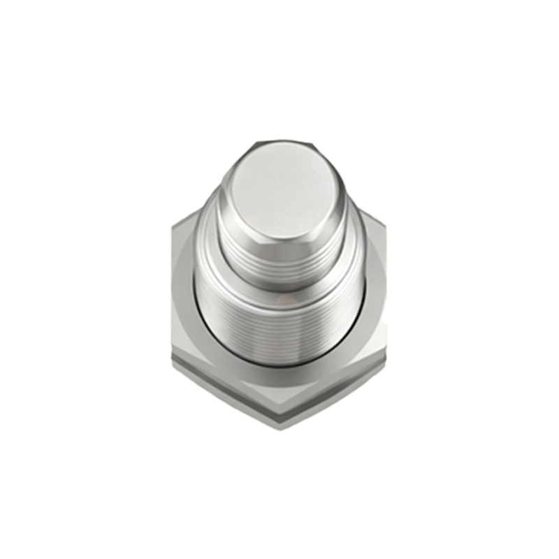
When analyzing a proximity sensor jack image, engineers should focus on several key details. First, the pin count and layout: Are there 2, 3, 4, or more pins? A 3-pin PNP sensor jack will have a different pinout than a 3-pin NPN. Second, the connector standard: Is it a standard M12, a proprietary rectangular shape, or a subminiature version? Third, the keying or coding: Many M12 connectors use an A-coded (standard sensor), B-coded (Fieldbus), or D-coded (Profinet) system, identifiable by a small groove or protrusion between specific pins. A high-quality image will make this coding visible. Fourth, the housing and sealing: The material (metal or plastic) and the presence of an O-ring groove indicate the environmental protection level. Finally, any labeling or markings near the jack, such as pin numbers (1, 2, 3, 4), voltage designations, or output symbols (PNP/NPN), are invaluable.
In practical applications, these images serve multiple purposes. During system design, they allow for accurate selection of mating cables and through-panel receptacles. In procurement, they ensure the exact sensor model is ordered. For maintenance technicians, a reference image aids in quickly identifying a faulty connection or verifying the correct spare part. Furthermore, including a clear jack image in internal technical documentation and asset management systems enhances clarity and reduces downtime.
To conclude, a detailed image of a proximity sensor jack is a fundamental element of its technical specification. It bridges the gap between schematic symbols and physical implementation. By understanding how to interpret the visual cues in these images—pin configuration, connector type, keying, and sealing—electrical and automation engineers can ensure robust, reliable, and error-free integration of sensing systems. Always cross-reference the jack image with the manufacturer's datasheet for the definitive pinout and electrical characteristics to guarantee optimal performance in your application.