Proximity sensors are essential components in modern industrial automation, providing non-contact detection of metallic or non-metallic objects. Proper wiring of their connectors is critical for reliable operation, safety, and system integrity. This guide outlines the fundamental steps and best practices for wiring proximity sensor connectors in industrial settings.
First, identify the sensor type and its electrical specifications. Proximity sensors generally fall into two categories: two-wire, three-wire, or four-wire models, with DC (PNP or NPN) or AC variants. Always refer to the manufacturer's datasheet for voltage ratings, current limits, and output configurations. For example, a three-wire DC sensor typically includes wires for power supply (brown or red), ground (blue or black), and signal output (black or white).
Begin by ensuring power is completely disconnected from the system. Use a voltage tester to confirm that no electrical charge is present in the cables. Prepare the necessary tools: wire strippers, crimping tools, screwdrivers, and appropriate connectors (e.g., M8, M12 connectors are common for sensors). Select cables that match the environmental conditions—such as oil-resistant or shielded cables for areas with high electromagnetic interference.
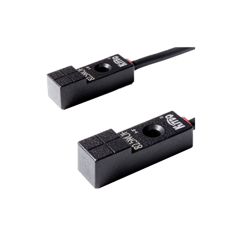
For a standard three-wire DC proximity sensor, follow these steps:
1. Strip the insulation from the sensor cables and the corresponding power/signal cables to the recommended length, usually 7-10 mm.
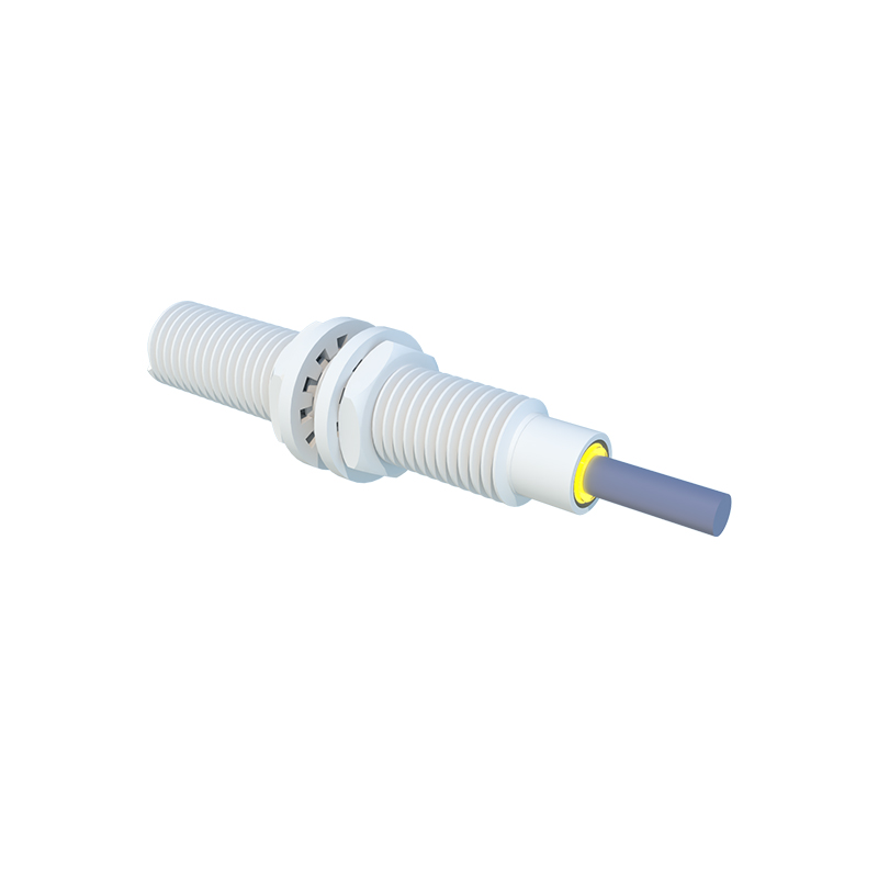
2. If using a pre-molded connector, insert each stripped wire into the designated terminal according to the pinout diagram. Typically, the brown wire connects to the positive supply (+V), blue to the negative or ground (0V), and black to the load or signal input. For PNP sensors, the output provides positive voltage; for NPN, it switches the ground.
3. Secure the wires using crimping ferrules or terminal screws to ensure a firm, gas-tight connection. Avoid loose strands that could cause short circuits.
4. Once wired, carefully mount the connector housing, ensuring seals are intact for IP-rated protection against dust and moisture.
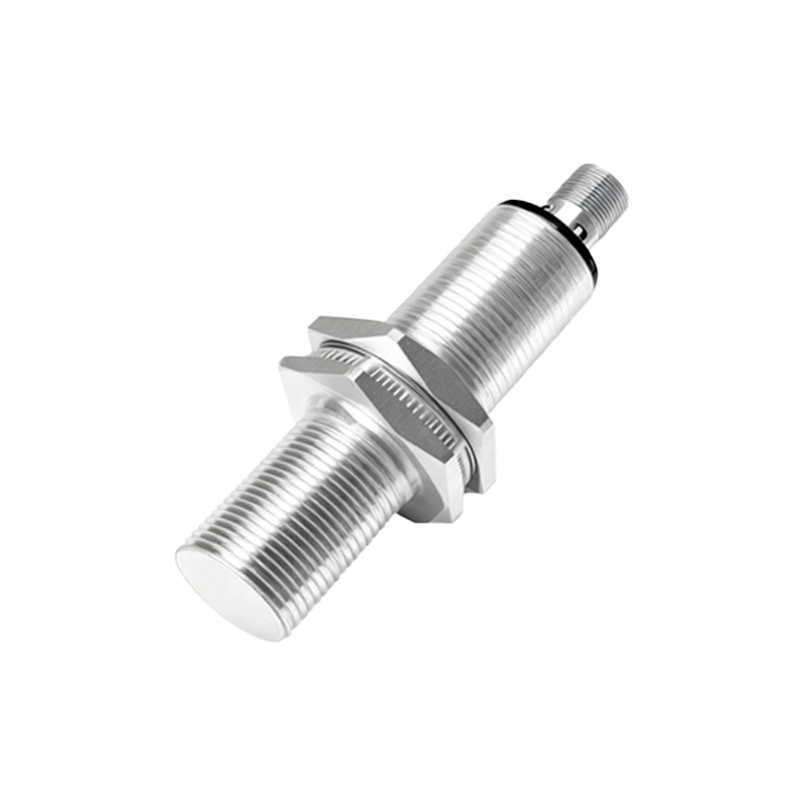
In the case of two-wire AC sensors, wiring is simpler: connect one wire to the AC line and the other to the load. However, note that these sensors may have leakage current, which can affect low-power loads; using a bypass resistor may be necessary. For four-wire sensors, which often include two signal outputs (e.g., NO and NC), verify the logic requirements of the connected controller (PLC or relay).
After wiring, perform thorough checks before energizing the system. Inspect for proper insulation, correct polarity, and secure mechanical fit. Use a multimeter to test continuity and ensure no short circuits exist between wires. Once powered, validate the sensor's operation by triggering it with a target object and monitoring the output signal with an oscilloscope or PLC input indicator.
Common pitfalls to avoid include mixing up PNP and NPN configurations, which can damage controllers, or using undersized cables that lead to voltage drop. Always adhere to local electrical codes and standards (e.g., IEC 60947-5-2 for proximity switches). For complex installations, consider using junction boxes or pre-wired connector systems to reduce errors and maintenance time.
Regular maintenance involves checking connector tightness and inspecting for corrosion or wear, especially in harsh environments. Properly wired proximity sensor connectors enhance system uptime, reduce downtime, and ensure safe, efficient automation processes. By following these guidelines, engineers and technicians can achieve reliable sensor integration in diverse industrial applications, from conveyor systems to robotic cells.