In the realm of industrial automation and motion control, proximity angular sensors play a pivotal role in ensuring precision, reliability, and efficiency. These sophisticated devices are engineered to detect the angular position or rotational speed of a target object without physical contact, making them indispensable in harsh environments where durability and non-intrusive measurement are paramount. This article delves into the fundamental operating principles, common technologies, and key applications of proximity angular sensors, providing a comprehensive overview for engineers and technical professionals.
At its core, a proximity angular sensor functions by detecting changes in a physical field—be it magnetic, capacitive, or inductive—caused by the rotational movement of a target. The most prevalent technology in industrial settings is the magnetic-based sensor, often utilizing Hall Effect or magnetoresistive principles. In a Hall Effect angular sensor, a permanent magnet is typically mounted on the rotating shaft. As the shaft turns, the magnetic field vector relative to a stationary Hall Effect integrated circuit (IC) changes. The Hall IC converts this changing magnetic flux density into a proportional voltage signal, which is then processed to determine the precise angular position. Magnetoresistive sensors operate similarly but rely on materials that change electrical resistance in response to an applied magnetic field, offering high resolution and accuracy.
Another significant category is inductive proximity angular sensors, such as resolvers and inductive encoders. A resolver is an analog electromechanical transducer. It consists of a rotor (connected to the shaft) with a primary excitation winding and a stator with two secondary windings arranged 90 degrees apart. An AC reference signal is applied to the rotor winding. As the rotor turns, the coupling between the rotor and stator windings varies, inducing sinusoidal voltages in the two stator windings. The amplitudes of these output signals are directly related to the sine and cosine of the shaft angle, allowing for absolute position calculation. Resolvers are renowned for their extreme ruggedness, high-temperature tolerance, and immunity to dust, oil, and vibration.
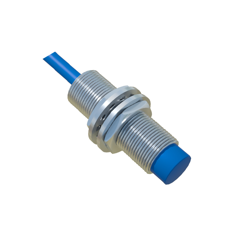
Capacitive angular sensors represent a third major technology. They measure angular displacement by detecting changes in capacitance between stationary plates and plates attached to the rotating member. The capacitance varies with the overlap area or the distance between these plates as the shaft rotates. These sensors are valued for their high resolution, low power consumption, and suitability for applications requiring very smooth torque, as they are completely contactless.
The selection of a specific proximity angular sensor technology hinges on application requirements. Key parameters include required accuracy, resolution, operating temperature range, environmental robustness (against contaminants, shock, and vibration), speed of rotation, output signal type (analog, digital, or fieldbus protocol), and cost. For instance, in electric power steering (EPS) systems in automotive engineering, Hall Effect sensors are widely used due to their good accuracy, compact size, and cost-effectiveness. In contrast, aerospace actuation systems or heavy-duty industrial robotics often employ resolvers for their unparalleled reliability in extreme conditions.
Signal processing is an integral part of these systems. Raw analog signals from the sensing element are conditioned, amplified, and often converted into digital formats like PWM (Pulse Width Modulation), SPI (Serial Peripheral Interface), or industry-standard analog outputs (0-10V, 4-20mA). Modern "smart sensors" incorporate microcontrollers to perform linearization, compensation for temperature drift, and diagnostics, providing processed digital data directly to the control system via protocols like CANopen or IO-Link.
Installation and alignment are critical for optimal performance. Proper air gap between the sensor and the target, concentricity of the rotating member, and mitigation of electromagnetic interference (EMI) are essential considerations. Shielding, careful routing of cables, and using twisted-pair wires for differential signals are standard practices to ensure signal integrity.
Looking ahead, trends in proximity angular sensing include further miniaturization, integration of multiple sensing functions (e.g., position and temperature), and enhanced diagnostic capabilities for predictive maintenance. The rise of Industry 4.0 and the Industrial Internet of Things (IIoT) is driving demand for sensors with embedded intelligence and seamless connectivity.
In conclusion, proximity angular sensors are fundamental components that translate mechanical rotation into actionable electrical data. Understanding their underlying principles—magnetic, inductive, and capacitive—empowers engineers to select and implement the optimal sensor technology. This ensures robust, precise, and reliable operation in diverse applications ranging from factory automation and renewable energy to advanced robotics and automotive systems, forming the backbone of modern motion feedback and control loops.