As a seasoned electrical engineer specializing in precision optical systems, I often encounter the need to service or replace laser autofocus sensors in industrial equipment, such as CNC machines, 3D printers, or automated inspection systems. These sensors are critical for maintaining accuracy, but their removal requires meticulous care to avoid damage to the sensitive component, the host machinery, and to ensure personnel safety from laser radiation. This guide provides a professional, step-by-step methodology for the safe and effective removal of a typical integrated laser autofocus sensor module.
1. Pre-Removal Preparation and Safety Protocol
Safety is paramount. Before any physical interaction, consult the equipment's official service manual for model-specific instructions and warnings. The most critical step is to ensure complete power isolation. Perform a lockout-tagout (LOTO) procedure: power down the main machine control, switch off the circuit breaker, and secure it with a personal lock and tag. Verify zero energy state using a multimeter at the sensor's power input terminals. Remember, capacitors within the driver circuit may retain charge; allow sufficient time for discharge or follow manual procedures for safe discharge.
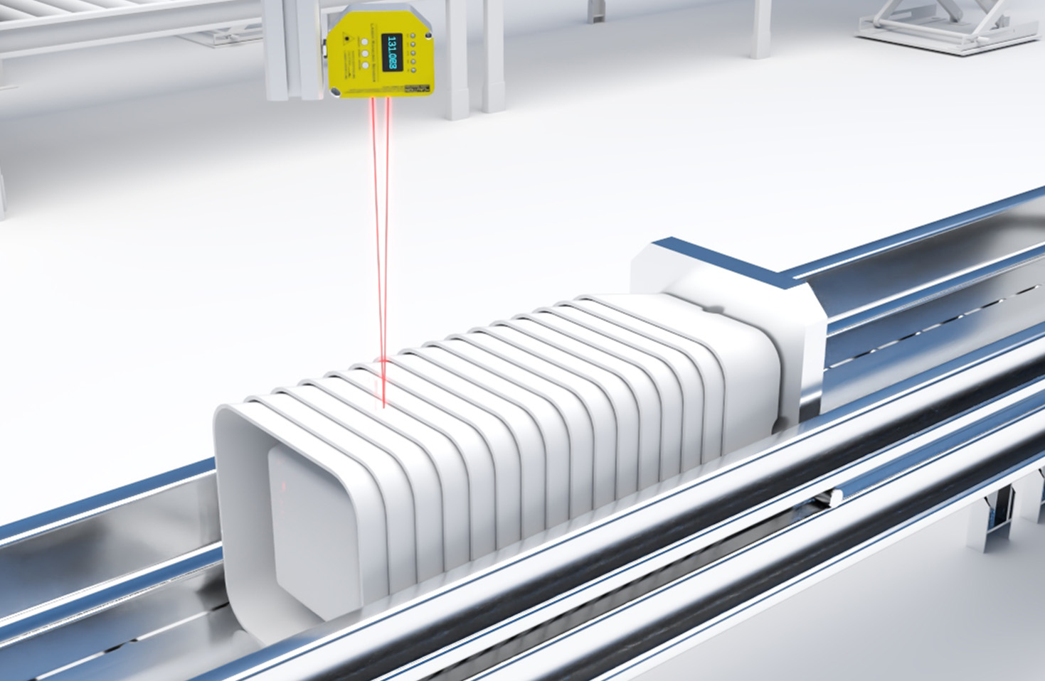
Next, address the laser itself. Class 2 or higher laser components can pose an eye hazard. Do not look directly into the beam aperture. If possible, disable the laser emission via software or a hardware disable pin before power-down as per the manual. Wear appropriate laser safety glasses rated for the sensor's specific wavelength during the entire procedure. Prepare a clean, static-free work surface. Gather necessary tools: precision screwdrivers, hex keys, needle-nose pliers, an anti-static wrist strap, and labeled containers for screws and small parts.
2. Disconnection and Interface Handling
Locate the sensor module. It is typically a compact unit mounted on a moving gantry or tool head. Identify all connections. These usually include a multi-pin electrical connector for power, control signals, and data feedback (e.g., a ribbon cable or a shielded cable with a plug), and possibly a pneumatic or coolant line if the module is air-cooled.
Do not pull on the cables. First, release any strain relief clips or cable ties securing the harness. For electrical connectors, carefully depress the locking tab (if present) and pull the connector straight out from its socket. Rocking or pulling at an angle can bend pins. For threaded couplings (like pneumatic lines), use the correct size wrench to avoid rounding the nuts. Immediately after disconnection, it is good practice to cover exposed connectors with dust caps or tape to prevent contamination.
3. Mechanical Unmounting and Extraction
The sensor is usually fastened with small, often metric, socket-head cap screws. Note the exact screw type, size, and quantity. Using the correctly sized hex key, loosen each screw in a cross-pattern sequence to avoid binding or warping the mounting bracket. Remove all screws and place them securely in a labeled container.
Before lifting the sensor, note its orientation and any alignment marks or dowel pins. The module may be precisely aligned. Gently separate the sensor from its mount. It might be held by friction or residual adhesive from a thermal pad. Use a flat, non-marring tool like a plastic spudger to carefully pry if necessary, applying force evenly at designated pry points if indicated in the manual. Avoid prying near the optical window or laser emitter.
Once free, lift the sensor module straight out. Handle it only by its chassis, never touching the optical surfaces (lens, emitter, receiver). Immediately place it in an anti-static bag for storage or transport. If the sensor is to be stored, place it in a rigid, protective case.
4. Post-Removal Procedures and Considerations
With the sensor removed, inspect the mounting area on the host machine. Clean the interface surface with isopropyl alcohol and a lint-free cloth to remove old thermal paste or debris. Inspect the cable connectors for any bent pins or damage. This is an opportune time to perform continuity checks on the cable harness if a fault is suspected.
If the removal is for replacement, ensure the new sensor is an exact match or a verified compatible unit. If the removal is for repair, label the sensor clearly with the machine ID, location, and fault description. Document the removal process, including any observations like unusual cable wear or corrosion, for future maintenance records.
Critical Reminders: Never apply excessive force. If a component does not move as expected, stop and re-evaluate. Static electricity can destroy the sensor's internal electronics; always use an anti-static wrist strap connected to the equipment's proper grounding point. Finally, never bypass safety interlocks designed to prevent laser operation during access.
Following this disciplined approach minimizes risk, prevents costly damage to sensitive opto-electrical components, and ensures a smooth process for subsequent reinstallation or repair. Always prioritize the manufacturer's specific guidelines over general advice, as designs can vary significantly.