Proximity switch sensors are essential components in modern industrial automation, widely used for object detection, position sensing, and machine safety. Understanding their wiring is crucial for ensuring reliable operation and minimizing downtime. This guide provides a practical overview of proximity sensor wiring, covering common types, wiring configurations, and best practices.
There are several types of proximity sensors, including inductive, capacitive, and photoelectric sensors. Inductive sensors detect metallic objects, capacitive sensors detect both metallic and non-metallic materials, and photoelectric sensors use light beams for detection. Each type has specific wiring requirements, but the fundamental principles remain similar.
Most proximity sensors have three wires: brown (positive), blue (negative), and black (output). The brown wire connects to the positive terminal of the power supply, typically 10-30V DC for DC sensors. The blue wire connects to the negative terminal or ground. The black wire is the output signal, which switches based on the sensor's detection state. For normally open (NO) configurations, the output closes when an object is detected; for normally closed (NC), it opens.
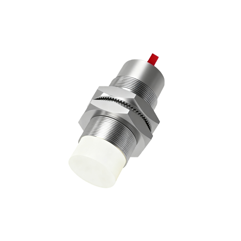
In wiring, it's vital to match the sensor's voltage and current ratings with the power supply and load. Overvoltage or excessive current can damage the sensor or connected equipment. Always refer to the manufacturer's datasheet for specific ratings. Use shielded cables in environments with electrical noise to prevent false triggering. Ground the shield at one end to avoid ground loops.
For AC-powered sensors, wiring differs slightly. Typically, they have two wires: one for live and one for neutral, with the output integrated. Ensure proper insulation and compliance with local electrical codes when handling AC wiring.
When connecting the output to a PLC or relay, verify the compatibility of the signal type (e.g., NPN or PNP for DC sensors). NPN sensors sink current to ground, while PNP sensors source current from the positive supply. Incorrect connections can lead to malfunction or damage.
In practice, start by disconnecting power before wiring. Strip the wire ends appropriately and use crimp connectors or terminal blocks for secure connections. Avoid loose wires that can cause short circuits. After wiring, perform a functional test by placing a target object within the sensor's sensing range and checking the output response with a multimeter or indicator.
Maintenance involves regular inspection for wear, corrosion, or damage to wires and connectors. Keep sensors clean from dust and debris, as contamination can affect performance. In harsh environments, consider using sensors with higher IP ratings for protection against moisture and dust.
Common issues in wiring include reversed polarity, incorrect voltage, and poor grounding. If a sensor fails to operate, check these aspects first. Also, ensure the sensing distance and object material are within specifications.
Advanced proximity sensors may feature additional wires for diagnostics or configuration. For example, some models have a teach-in function for adjusting sensitivity, requiring temporary connections per the manual. Always follow manufacturer instructions for such features.
In summary, proper wiring of proximity switch sensors is key to efficient automation systems. By understanding the basics, adhering to safety protocols, and performing regular checks, engineers can ensure long-term reliability and optimal performance.