In the realm of industrial automation and electrical engineering, schematic diagrams serve as the universal language. These blueprints, composed of standardized graphical symbols, allow engineers and technicians across the globe to design, troubleshoot, and maintain complex systems. Among the myriad of components represented, proximity sensors hold a critical role in non-contact detection and position sensing. A clear understanding of their graphical symbols is paramount for accurate interpretation of circuit functionality.
Unlike basic components such as resistors or capacitors, the symbols for proximity sensors are more descriptive, often conveying both the sensor's operating principle and its output type. The foundation of these symbols is typically a square or a rectangle, representing the sensor housing. Within or adjacent to this shape, specific markings indicate the technology employed.
The most common distinction is between inductive and capacitive sensors. An inductive proximity sensor, designed to detect metallic objects, is symbolized by a coil within the square, reminiscent of an inductor symbol. Four short, parallel lines are often drawn perpendicular to the sensor face, representing the electromagnetic field. The standard IEC symbol features a square with a diamond inside, flanked by two vertical lines on the sensing side. For a capacitive sensor, used for detecting both metallic and non-metallic materials, the symbol often includes two parallel plates or a icon resembling a capacitor adjacent to the square, indicating its principle of sensing changes in capacitance.
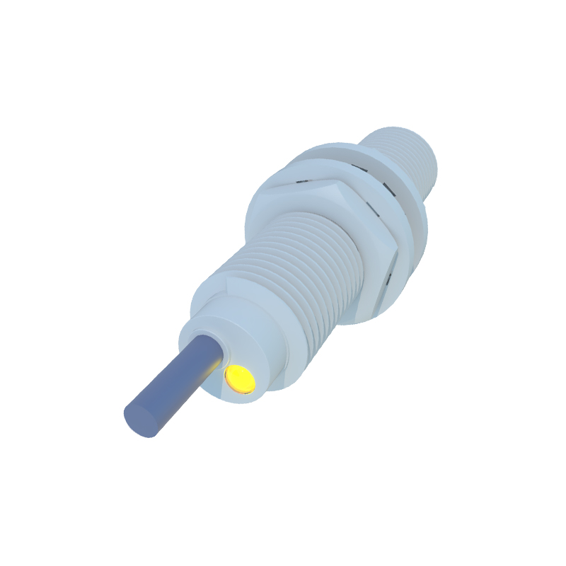
Perhaps the most crucial part of the symbol is the output representation. This defines how the sensor interfaces with the control system, typically a Programmable Logic Controller (PLC). The output is denoted by a small diagram placed inside the bottom of the sensor square.
PNP (Sourcing) Output: Shown as an arrow pointing outward from the sensor symbol, indicating that the sensor switches the positive voltage line to the load.
NPN (Sinking) Output: Shown as an arrow pointing inward toward the sensor symbol, indicating that the sensor switches the negative or ground line to the load.
Analog Output: Often represented by a wave symbol inside the square or the letters "AOUT," denoting a continuous voltage or current signal proportional to the sensing distance.
Namur Output: A specialized intrinsically safe output for hazardous areas, often shown with a specific letter "N" or a unique icon as per manufacturer documentation.
Furthermore, the status of the output—normally open (NO) or normally closed (NC)—is a fundamental concept. In a NO configuration, the output circuit is open (off) when no target is present and closes (on) when a target is detected. The opposite is true for NC. While sometimes implied by the circuit context, this state is occasionally indicated by a break in the output line for NO, or by a specific annotation like "NC" near the symbol.
It is essential to consult the legend or specific manufacturer's datasheet for any schematic, as minor variations can exist. For instance, a ultrasonic sensor might have a small "U" or wave icon, while a photoelectric sensor (through-beam, retro-reflective, or diffuse) is universally represented by a square with a diode-like arrow for the emitter and a phototransistor-like symbol for the receiver, connected by dashed lines representing the light beam.
Misinterpreting these symbols can lead to incorrect wiring, faulty logic programming, or extended downtime. For example, connecting a PNP sensor to an NPN input module, or vice versa, will result in a non-functional circuit. Similarly, confusing an NC symbol for an NO can cause a machine to behave in the opposite manner, potentially creating a safety hazard.
In practice, when analyzing a ladder logic diagram or a power circuit, the proximity sensor symbol provides immediate insight. You can discern if it detects metal (inductive) or any material (capacitive), whether it provides a discrete on/off signal (PNP/NPN) or a variable measurement (analog), and the logical state of its output in the resting condition. This allows for rapid diagnostics; if a machine fault occurs, an engineer can trace the sensor's symbol, understand its expected behavior, and verify its real-world operation with a multimeter or the PLC's input status indicators.
Mastery of these graphical symbols is not merely an academic exercise but a practical necessity. It bridges the gap between the abstract world of circuit diagrams and the physical reality of sensors on a production line, enabling efficient design, seamless commissioning, and effective maintenance of modern automated systems. Always remember, the symbol tells the sensor's story—its capability, its action, and its role in the broader control narrative.