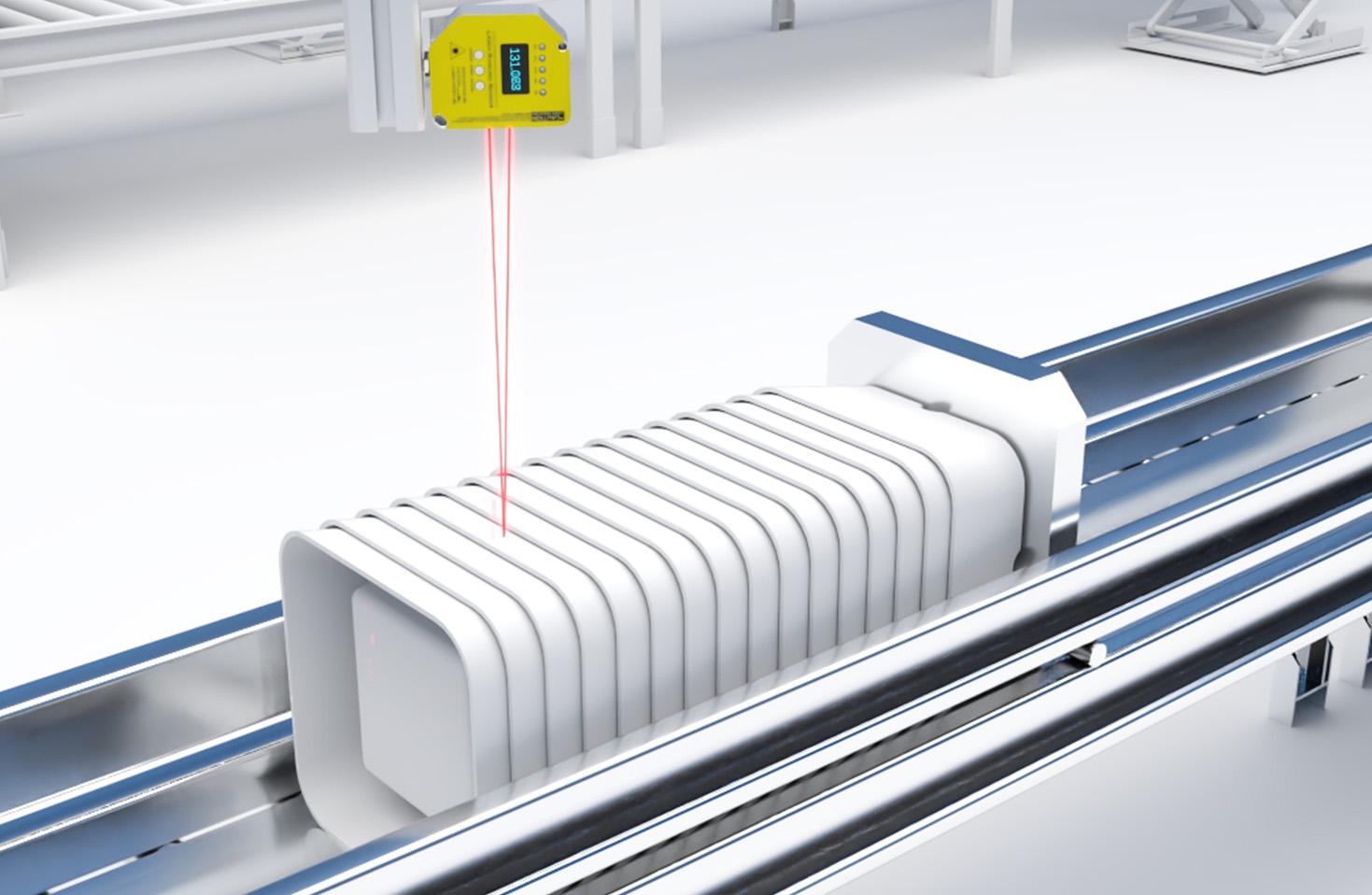
Laser sensors are critical components in modern industrial automation, offering high precision for detection, measurement, and positioning tasks. Understanding their wiring principles is essential for ensuring reliable operation and system integration. This article outlines the fundamental wiring concepts for common laser sensor types, including diffuse, retro-reflective, and through-beam sensors, focusing on electrical connections, interface compatibility, and safety considerations.
Most industrial laser sensors operate on DC power, typically within a range of 10-30 VDC. The power supply must be stable and adequately rated to handle the sensor's current draw, usually specified in milliamperes (mA). Incorrect voltage or excessive ripple can lead to erratic performance or permanent damage. Always verify the sensor's datasheet for exact requirements before connecting power.

A standard three-wire configuration is prevalent: one wire for DC positive (brown or red), one for DC negative (blue or black), and one for the output signal (black, white, or another color). The output can be either NPN (sinking) or PNP (sourcing), determining how the sensor interfaces with the controller (e.g., PLC). In NPN wiring, the output switches the negative side of the load to ground, common in Asian and European systems. In PNP wiring, the output switches the positive side, often used in North America. Mismatching these can cause malfunction, so confirm the controller's input type.
Four-wire sensors may include separate wires for a second output or diagnostic functions. Some advanced models feature programmable outputs or IO-Link communication, allowing digital parameter setting and data exchange. For these, follow the manufacturer's pinout diagram precisely. Shielded cables are recommended to minimize electrical noise, especially in environments with motors or variable frequency drives. Connect the shield to ground at one end only, usually at the controller, to prevent ground loops.
Through-beam sensors consist of separate emitter and receiver units. The emitter typically has two wires for power, while the receiver includes power and output wires. Align the units accurately to ensure the laser beam strikes the receiver's detection area. Retro-reflective sensors use a reflector; wiring is similar to diffuse types, but alignment with the reflector is crucial. Diffuse sensors have all electronics in one housing, simplifying wiring but requiring careful adjustment of sensing distance and sensitivity.
Always disconnect power before wiring to prevent short circuits or electric shock. Use appropriate wire gauges and connectors rated for the current and environmental conditions (e.g., IP ratings for dust and moisture). After connections, test the sensor with a multimeter or oscilloscope to verify output behavior. For complex setups, refer to application notes or consult technical support. Proper wiring not only ensures functionality but also extends sensor lifespan and maintains system safety.
In summary, laser sensor wiring involves selecting the correct power supply, matching output types to the control system, and adhering to noise-reduction practices. As technology evolves, integrating smart sensors with digital interfaces may require additional steps, but the core principles of secure, accurate connections remain paramount for optimal performance in automation, robotics, and quality control applications.