In the realm of industrial automation and precision measurement, laser sensors are indispensable tools. Their ability to provide non-contact, high-accuracy distance and position measurements makes them critical for quality control, robotics, and machine guidance. However, a frequently overlooked yet crucial factor affecting their performance is sensor tilt. Laser sensor tilt refers to the angular deviation between the sensor's optical axis and the ideal perpendicular line to the target surface. This misalignment, even if minute, can introduce significant measurement errors, compromising system integrity and product quality.
The core operating principle of most industrial laser sensors, such as triangulation or time-of-flight sensors, relies on a specific geometric relationship. In a standard triangulation sensor, a laser diode projects a spot onto a target. The reflected light is focused onto a position-sensitive detector (PSD) or a CMOS/CCD array. The position of the reflected spot on the detector correlates directly to the distance to the target. This correlation is calibrated assuming the sensor is perfectly perpendicular to a reference surface. When tilt is introduced, this geometric relationship distorts. The incident angle changes, causing the reflected spot to shift on the detector not solely due to distance variation but also due to the angular misalignment. This results in a measured distance that is either shorter or longer than the true perpendicular distance, a phenomenon known as cosine error. For instance, with a 5-degree tilt on a surface 100mm away, the cosine error can already exceed 0.38mm, which is unacceptable in micron-level precision tasks.
The impacts of unmanaged laser sensor tilt are multifaceted. Firstly, it causes systematic measurement inaccuracies. These errors are not random; they follow a predictable pattern based on the tilt angle and the measurement distance, but they directly degrade the stated accuracy of the sensor. Secondly, tilt can affect the size and shape of the laser spot on the target. An oblique incidence elongates the spot, potentially reducing intensity and degrading signal quality, especially on rough or diffuse surfaces. This can lead to unstable readings or even signal loss. Thirdly, in applications involving profile scanning or surface contouring, sensor tilt can skew the entire captured profile, rendering dimensional analysis faulty. In robotic bin-picking or assembly, a tilted sensor may misrepresent the true position and orientation of a part, leading to failed grasps or misalignments.
Mitigating the effects of laser sensor tilt involves a combination of mechanical design, careful installation, and software compensation. The first line of defense is precise mechanical mounting. Using high-quality adjustable brackets with fine pitch screws and integrated bubble levels or digital inclinometers during installation is essential. For critical applications, kinematic mounts or auto-collimators can be used for ultra-precise alignment. The mounting structure itself must be rigid and stable to prevent thermal drift or vibration from inducing tilt over time.
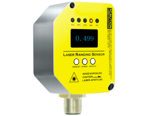
When mechanical alignment to perfect perpendicularity is impractical, calibration and software compensation become vital. A common method is to perform a two-axis tilt calibration. The sensor measures a known flat reference plate at various known distances and at controlled tilt angles (both in X and Y axes). This data is used to generate a complex error map or a correction algorithm. In modern smart sensors, this compensation can be embedded in the sensor's firmware. The controller can then output a corrected value that accounts for the known tilt angle, often provided by an external inclinometer or calculated through a multi-point measurement scheme.
Furthermore, the choice of sensor type can influence tilt sensitivity. Confocal chromatic sensors, for example, are generally less sensitive to mild tilt compared to standard triangulation sensors because they use a different optical principle. However, no sensor is entirely immune. Understanding the specific tilt specifications in the sensor's datasheet—often given as an allowable tilt angle for a specified accuracy loss—is a critical step in selection.
In practice, establishing a routine for checking and recalibrating for tilt is part of good maintenance, especially in environments with temperature fluctuations or mechanical shocks. A simple verification can involve measuring a precision gauge block or a flat at two different known positions and checking for deviation from expected values.
In conclusion, laser sensor tilt is a subtle but powerful source of error in precision measurement systems. Acknowledging its presence and implementing robust strategies for minimization and compensation are hallmarks of sophisticated engineering practice. By ensuring optimal sensor alignment or accurately compensating for its absence, engineers can unlock the full potential of laser measurement technology, guaranteeing the reliability, accuracy, and efficiency demanded by modern industrial applications.