In the realm of industrial automation and precision measurement, laser distance sensors have become indispensable tools. Among the various communication protocols available, RS-485 stands out as a robust and widely adopted standard for interfacing these sensors with control systems. This article delves into the technical intricacies, advantages, and practical implementation of laser distance sensors utilizing 485 communication, providing a thorough understanding for engineers and system integrators.
RS-485, formally known as TIA-485-A, is a standard defining the electrical characteristics of drivers and receivers for use in balanced digital multipoint systems. Its primary strength lies in its ability to support long-distance communication—up to 1200 meters—and its noise immunity due to differential signaling. This makes it exceptionally suitable for industrial environments where electromagnetic interference (EMI) is prevalent. A laser distance sensor equipped with a 485 interface typically transmits measured distance data as a serial data stream, often formatted according to protocols like Modbus RTU, which is a common application-layer protocol built upon the RS-485 physical layer.
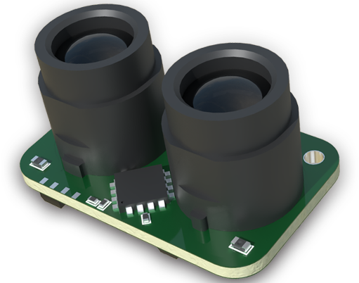
The operational principle of a laser time-of-flight (ToF) sensor is based on emitting a laser pulse and measuring the time it takes for the reflection to return. The sensor's internal processor calculates the distance with high accuracy. This digital distance value is then packetized by the sensor's communication module. Through the 485 transceiver, the data is converted into a differential voltage signal. The 'A' and 'B' lines carry complementary signals, and the receiver interprets the difference between them, effectively rejecting common-mode noise picked up along the cable. This ensures data integrity even in electrically noisy settings such as manufacturing floors with heavy machinery.
Integrating a 485-based laser sensor into a system involves several key considerations. First is network topology: RS-485 supports a multi-drop architecture, allowing up to 32 unit loads on a single bus. This means multiple laser sensors can be connected to a single master device (like a PLC, PC, or microcontroller) using a daisy-chain or trunk-and-drop topology, significantly simplifying wiring and reducing infrastructure costs. Termination resistors (typically 120Ω) at both ends of the bus are crucial to prevent signal reflections that can cause data corruption. Proper grounding and shielding of the twisted-pair cable are equally vital to maintain signal quality.
From a software perspective, communication is typically managed through a serial port. The master device sends a query frame containing the sensor's unique address (or broadcast address), a function code (e.g., "read holding registers" in Modbus), and a checksum. The addressed sensor responds with a data frame containing the measured value. The data format, baud rate (common rates are 9600, 19200, 38400 bps), parity, and stop bits must be configured identically on both the sensor and the master. Most modern sensors offer configuration via software or dip switches, allowing engineers to set these parameters and the device address easily.
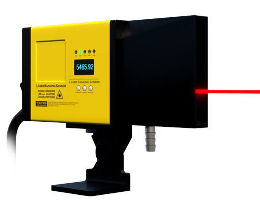
The advantages of using 485 communication for laser distance sensors are manifold. Reliability in Harsh Environments: The differential signaling provides excellent noise immunity, ensuring stable operation near motors, VFDs, and welding equipment. Long-Distance Capability: It enables monitoring and control over vast areas of a factory or outdoor site from a central location. Cost-Effectiveness: The ability to network multiple sensors on a single two-wire bus drastically reduces cabling and interface hardware costs compared to point-to-point analog or USB connections. Interoperability: The prevalence of Modbus RTU over 485 ensures compatibility with a vast ecosystem of PLCs, SCADA systems, and HMIs from different manufacturers.
Common applications include warehouse automation for pallet positioning and height measurement, roll diameter measurement in paper and steel mills, crane positioning and anti-collision systems, and precise level monitoring in silos and tanks. In each case, the 485 network reliably aggregates data from multiple sensor points to a central controller for real-time decision-making.
When selecting a 485 laser sensor, key specifications to evaluate include measurement range, accuracy, repeatability, laser class (Class 2 is common for industrial use), response time, and the specific communication protocol supported. It is also essential to verify the sensor's compliance with relevant industrial standards for EMC and environmental protection (IP rating).
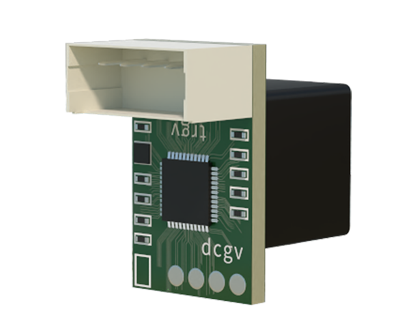
In conclusion, the integration of laser ranging technology with the robust RS-485 communication standard creates a powerful solution for industrial measurement and control. Its combination of precision, noise immunity, and networking flexibility makes it a cornerstone technology for engineers building resilient and scalable automation systems. Proper understanding of its electrical and protocol requirements is fundamental to deploying a successful and maintenance-free sensor network.