In the realm of precision measurement and industrial automation, laser displacement sensors are indispensable tools for non-contact, high-accuracy distance and profile measurement. A critical, yet often overlooked, factor that significantly influences measurement accuracy and reliability is the sensor's tilt angle relative to the target surface. This angle, defined as the deviation from the ideal perpendicular (90-degree) incidence, is not merely a mounting consideration but a fundamental parameter in the measurement equation.
When a laser displacement sensor is perfectly perpendicular to a target, the emitted laser beam reflects directly back along the same path to the receiver. This ideal scenario yields the highest signal strength and the most accurate measurement of the true standoff distance. However, in practical applications, achieving and maintaining a perfect 0-degree tilt is often impossible due to spatial constraints, target geometry, or mounting limitations. Introducing a tilt angle creates a geometric condition where the measured distance is the hypotenuse of a right triangle, while the desired value is typically the perpendicular leg. This results in a cosine error, where the sensor reads a value longer than the actual perpendicular distance. For small angles, this error is minimal, but it grows significantly with increasing tilt. For instance, at a 10-degree tilt, the cosine error is approximately 1.5% of the measured distance.
Beyond geometric error, tilt angle profoundly affects the quality of the received laser signal. Most laser displacement sensors, particularly those using triangulation principles, rely on capturing diffusely reflected light from the target surface. The intensity and distribution of this diffuse reflection follow Lambert's cosine law, meaning the perceived brightness decreases as the angle of incidence increases. A large tilt angle can lead to a weak or scattered return signal, pushing the sensor towards its signal-to-noise ratio limits. This can cause measurement instability, dropout, or complete failure, especially on low-reflectivity or dark surfaces. Conversely, on specular (mirror-like) surfaces, an incorrect tilt can cause the strong specular reflection to miss the receiver entirely, also leading to measurement failure.
The impact of tilt is not uniform across all sensor types. Confocal chromatic and spectral interferometry sensors are generally more tolerant of tilt due to their different optical principles, which rely on detecting wavelength shifts rather than the position of a light spot. However, they still have defined acceptable angular ranges. For standard laser triangulation sensors, manufacturers specify a maximum allowable tilt angle, often in the range of ±10 to ±15 degrees, beyond which performance degrades or the sensor may not operate. It is crucial to consult the sensor's datasheet for these specifications.
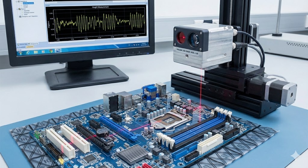
Managing and optimizing the tilt angle is therefore a cornerstone of successful sensor integration. The first step is meticulous mechanical design and alignment during installation. Using precision mounting brackets, adjustable stages, and alignment tools like autocollimators or digital angle gauges can ensure the initial angle is within tolerance. For dynamic applications or on moving platforms, the mechanical rigidity of the mount is paramount to prevent angle drift due to vibration or thermal expansion.
Software and calibration offer powerful tools for compensation. Many modern laser sensor controllers feature built-in functions for tilt compensation. By inputting the known, fixed tilt angle (measured during installation), the controller can automatically apply a cosine correction to the raw distance data, outputting the true perpendicular distance. For applications involving profile scanning over curved or angled surfaces, advanced sensors with "2D" or "profile" output can internally calculate surface orientation and correct measurements in real-time.
In practice, engineers must perform a trade-off analysis. Sometimes, a deliberate tilt is introduced to avoid obstacles, prevent specular reflection issues, or to measure specific features like step heights. In such cases, the angle must be precisely characterized and compensated for. The choice of sensor model should also consider its angular characteristics. For challenging environments with potential for large or variable tilt, selecting a sensor with a wider acceptance angle or a confocal type may be the optimal solution.

In conclusion, the laser displacement sensor tilt angle is a pivotal parameter that bridges theoretical accuracy and practical performance. Neglecting its effects can introduce significant, systematic errors and compromise system reliability. A disciplined approach—encompassing careful mechanical alignment, understanding of sensor specifications, and strategic use of compensation techniques—is essential to harness the full potential of laser displacement sensing technology. By mastering tilt angle management, engineers ensure robust, accurate, and dependable measurements that form the reliable foundation for quality control, robotics guidance, and automated inspection systems across manufacturing, electronics, and automotive industries.