Proximity switch sensors are essential components in modern industrial automation, providing non-contact detection of metallic or non-metallic objects. Understanding their wiring diagrams is crucial for proper installation, operation, and troubleshooting. This guide details the standard wiring configurations for common types of proximity sensors, including two-wire, three-wire, and four-wire models, along with practical considerations for integration into control systems.
A proximity sensor typically consists of a sensing element, oscillator, amplifier, and output circuit. The wiring diagram visually represents the electrical connections between the sensor and the power supply, load (such as a PLC input, relay, or indicator), and sometimes a controller. Correct wiring ensures reliable operation and prevents damage to the sensor or connected equipment.
Two-Wire Proximity Sensor Wiring
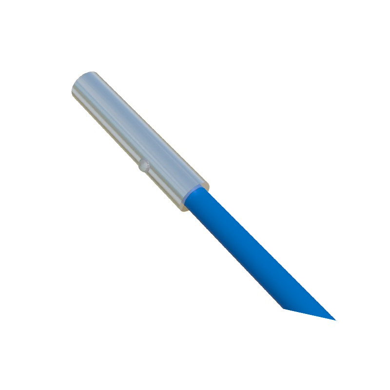
The two-wire sensor is the simplest type, acting like a switch in series with the load. It has only two terminals: one for connecting to the positive voltage supply (often labeled +V or L+) and the other for connecting to the load. The load is then connected back to the negative supply (L- or common). These sensors are polarity-sensitive in DC configurations. The wiring diagram shows a direct series connection. A key consideration is the residual current or leakage current when the sensor is off, which must be lower than the minimum holding current of the load (e.g., a relay) to prevent unintended activation.
Three-Wire Proximity Sensor Wiring
This is the most common configuration, offering separate power and output wires for better performance. The three wires are typically:
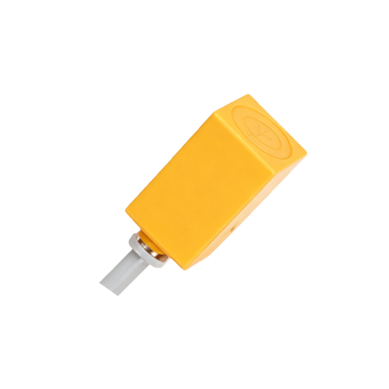
1. Brown (or Red): Connected to the positive DC supply voltage (e.g., +24VDC) or the live terminal for AC models.
2. Blue: Connected to the negative DC supply (0VDC) or the neutral for AC models.
3. Black (or White): The output signal wire.
There are two primary output types, each with a distinct wiring diagram:
NPN (Sinking) Output: The black wire switches the negative (0V) side of the load. In the diagram, one side of the load is connected to the positive supply (+V), and the other side is connected to the sensor's black output wire. When the sensor detects an object, it connects the black wire to the internal blue wire (0V), completing the circuit to ground and thus "sinking" the current.
PNP (Sourcing) Output: The black wire switches the positive voltage side of the load. Here, one side of the load is connected to 0V, and the other side is connected to the black wire. Upon detection, the sensor connects the black wire to the internal brown wire (+V), "sourcing" current to the load.
A four-wire sensor typically includes both an NPN and a PNP output wire (often black and white), plus the standard brown and blue power wires. The wiring diagram shows how these two independent outputs can be connected to different loads, providing flexibility for controlling multiple devices or interfacing with different PLC input card types (sinking or sourcing).
Wiring to a Programmable Logic Controller (PLC)
Matching the sensor output type to the PLC input type is critical. A PLC with sinking inputs (common positive) requires PNP sensors. A PLC with sourcing inputs (common negative) requires NPN sensors. The wiring diagram illustrates the complete loop: power supply to sensor, sensor output to the PLC's input terminal, and the PLC's common terminal back to the power supply.
Key Installation and Safety Practices
1. Always refer to the manufacturer's datasheet and diagram for specific wire colors, voltage ratings, and connection points.
2. Disconnect power before making any connections.
3. Use proper cable glands and conduits in harsh industrial environments to protect wires from damage, oil, and moisture.
4. Ensure correct voltage (e.g., 10-30VDC for many models) and do not exceed the maximum current rating of the output.
5. Maintain adequate sensing distance and avoid mounting sensors too close to each other to prevent mutual interference.
6. For AC-powered sensors, correctly identify the live (L) and neutral (N) terminals.
Troubleshooting Common Wiring Issues
Sensor not powering on: Check power supply voltage and polarity. Verify connections on brown and blue wires.
No output signal: Confirm the load is compatible and functional. Check if the detected object is within the sensing range and is of the correct material. Use a multimeter to measure voltage at the output wire relative to the blue wire (for PNP) or brown wire (for NPN) during activation.
Intermittent operation: Look for loose