In industrial automation and control systems, few components are as critical yet as frustrating as proximity sensors when they begin to fail intermittently or consistently. As a seasoned electrical engineer, I have diagnosed countless instances of "sensor always alarming" or "false triggering." The issue is rarely that the sensor itself is inherently faulty from the outset. More often, the root cause lies in the application environment, installation practices, or external interference. Understanding the underlying principles of inductive, capacitive, and ultrasonic proximity sensors is the first step toward a solution.
A predominant cause of erratic behavior is incorrect installation and mounting. Proximity sensors have specific sensing ranges and require precise positioning relative to the target. A common error is mounting the sensor too close or too far from the target object. If too close, physical contact or excessive stress on the sensing field can occur. If too far, the sensor operates at the edge of its nominal range, making it susceptible to minor variations in target position, temperature, or voltage. Furthermore, the sensor must be mounted securely to prevent vibration-induced movement, which can cause fluctuating signals. For inductive sensors, ensure the target material is ferrous or non-ferrous metal as specified; attempting to detect non-metallic objects will result in failure. For capacitive sensors, unintended changes in the dielectric constant of the surrounding area (like humidity or contamination buildup) can trigger false readings.
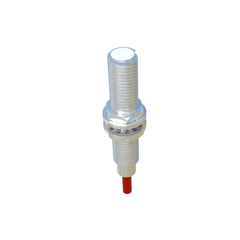
Electrical noise and interference represent another major category of problems. Industrial environments are saturated with electromagnetic noise from variable frequency drives (VFDs), motors, solenoids, welding equipment, and communication lines. This noise can easily couple into sensor cables, especially if shielded cables are not used or are improperly grounded. Always use the manufacturer-recommended cable type, typically a shielded and twisted-pair cable. The shield should be grounded at only one end, typically at the controller or PLC panel, to avoid ground loops. Power supply quality is equally crucial. Voltage spikes, sags, or ripple on the DC supply line can destabilize the sensor's internal circuitry. Measure the supply voltage at the sensor terminals during operation to ensure it remains within the specified tolerance, often 10-15% of the nominal value. Adding a dedicated, regulated power supply or line filters for sensitive sensors can resolve many unexplained errors.
Environmental factors are relentless adversaries. Temperature extremes can affect both the sensor's electronics and the properties of the target. High temperatures may cause the oscillator circuit in an inductive sensor to drift, reducing its effective sensing distance. Condensation or direct exposure to coolants, oils, and metal chips can physically damage the sensor face or create a conductive bridge that a capacitive sensor interprets as a target. Always select a sensor with an appropriate Ingress Protection (IP) rating for its location. For instance, an IP67-rated sensor can withstand temporary immersion and is suitable for washdown areas, while IP69K is for high-pressure, high-temperature cleaning. Chemical exposure can degrade sensor housing and seals over time, leading to internal corrosion.
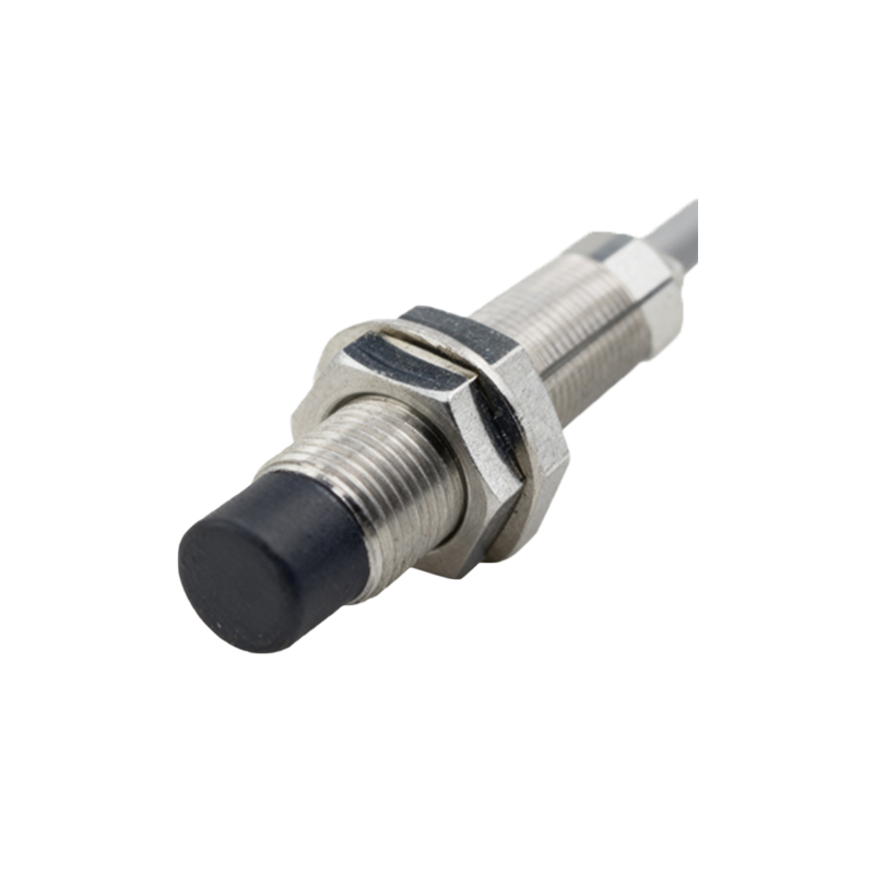
The load and wiring configuration must be meticulously checked. Exceeding the sensor's maximum switching current or load can damage its output transistor. Conversely, a load that is too small (like a high-impedance PLC input) might not draw enough current to reliably switch, leading to erratic behavior. Always consult the datasheet for minimum and maximum load specifications. For 3-wire DC sensors, ensure correct polarity and that the Brown (positive), Blue (negative), and Black (output) wires are connected properly. A swapped wire can instantly destroy the device. For 2-wire AC/DC sensors, verify there is sufficient residual current when "off" to power the sensor internally. A common oversight is neglecting the leakage current, which can keep a PLC input slightly energized, causing logic errors.
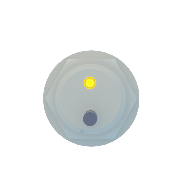
Finally, do not overlook mechanical wear and component aging. The sensing face can become scratched or coated with a thick layer of grime, attenuating the electromagnetic or ultrasonic field. Internally, components like capacitors can degrade over years of service, leading to timing errors or reduced sensitivity. Regular preventive maintenance, including visual inspection, cleaning with appropriate solvents, and functional testing with a known target at a known distance, is essential.
Systematic troubleshooting is key. Start by isolating the sensor: disconnect it from the machine logic and test its output directly with a multimeter or oscilloscope in response to a controlled target movement. This determines if the fault lies with the sensor or elsewhere in the control system. Verify all mechanical alignments. Review electrical drawings for proper grounding schemes. By methodically eliminating potential causes—mechanical, electrical, and environmental—you will identify the true culprit and restore reliable operation, minimizing costly downtime.