Proximity sensors are indispensable components in modern industrial automation, enabling non-contact detection of metallic or non-metallic objects. Correct wiring is paramount to ensure reliable operation, safety, and longevity of both the sensor and the control system. This guide provides a comprehensive, step-by-step approach to wiring common types of proximity sensors, adhering to standard industry practices.
Understanding Proximity Sensor Fundamentals
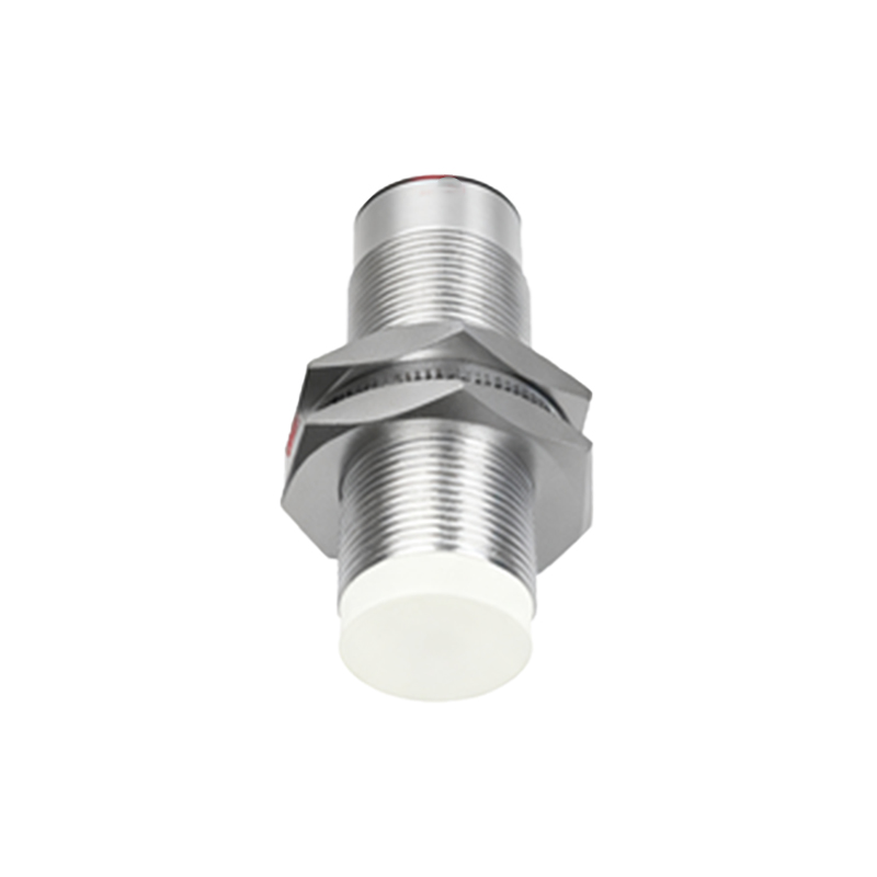
Before connecting wires, it's crucial to understand the sensor's type and specifications. The two primary categories are Inductive (detecting metallic objects) and Capacitive (detecting both metallic and non-metallic objects). Furthermore, sensors are classified by their output configuration: NPN (sinking) and PNP (sourcing), and by the number of wires: 2-wire, 3-wire, or 4-wire (which often include two separate outputs). Always consult the manufacturer's datasheet for the specific model's electrical characteristics, such as operating voltage (commonly 10-30V DC or 90-250V AC), current rating, and output type.
Essential Safety Precautions
1. Power Disconnection: Always isolate and lock out all power sources to the control panel and the sensor circuit before beginning any wiring work.
2. Proper Tools: Use insulated tools appropriate for the wire gauge and terminal types.
3. Wire Selection: Select wires with a suitable gauge (AWG) for the expected current load and environmental conditions (e.g., oil resistance, temperature rating).
4. Documentation: Refer to the system schematic diagram to verify the intended circuit design.
Wiring Procedures by Sensor Type
1. 2-Wire AC/DC Sensors
These sensors are wired in series with the load. They function similarly to a switch.
Procedure: Connect one wire to the positive DC supply or one side of the AC line (L1). Connect the other wire to one terminal of the load (e.g., a PLC input, relay coil). The other terminal of the load is then connected to the negative DC supply or the other side of the AC line (Neutral). Polarity is typically not critical for AC models but is essential for DC models.
Key Consideration: A 2-wire sensor has a residual leakage current even when "off." Ensure the connected load's minimum operating current is above this leakage value to prevent false triggering.
2. 3-Wire DC Sensors (NPN and PNP)
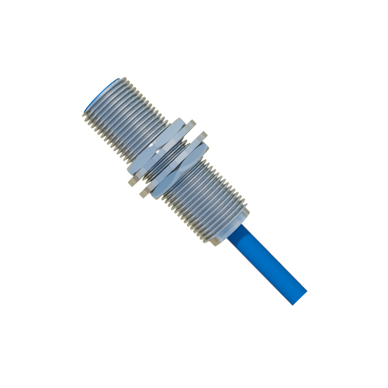
This is the most common configuration in DC systems. The three wires are typically Brown (V+), Blue (V- or Common), and Black (Output Signal).
General Steps:
a. Connect the Brown wire to the positive DC supply voltage (e.g., +24V).
b. Connect the Blue wire to the negative DC supply voltage (0V or Common).
c. Connect the Black (output) wire to the input of your controller (e.g., PLC digital input).
For a PNP (Sourcing) Sensor: The Black wire outputs a positive voltage when activated. Therefore, the PLC input module must be configured to receive a sourcing signal (typically connected to 0V internally).
For an NPN (Sinking) Sensor: The Black wire sinks current to 0V when activated. Therefore, the PLC input module must be configured to receive a sinking signal (typically connected to +V internally).
Crucial Rule: The sensor's power supply (Brown/Blue) and the load's power supply must share the same common (0V) reference point.
3. 4-Wire DC Sensors
These sensors provide two complementary outputs (e.g., one PNP-NO and one PNP-NC, or one NPN and one PNP). They follow the same power connection principles as 3-wire sensors. The two output wires (commonly Black and White) are connected to two separate load devices or inputs, providing normally-open and normally-closed functionality from a single unit.
Testing and Commissioning
After wiring is complete and visually inspected for secure connections and correct routing, follow this sequence:
1. Restore power to the control system.
2. Use a multimeter to verify the voltage between the sensor's Brown and Blue wires matches the specified range.
3. Without a target present, measure the voltage on the output (Black) wire. For a PNP sensor, it should be near 0V (off state). For an NPN sensor, it should be near the supply voltage (off state). Consult the datasheet for exact logic levels.
4. Introduce a valid target object within the sensor's sensing range. The output state should