Proximity sensors are indispensable components in modern industrial automation, robotics, and machinery. Their ability to detect the presence or absence of an object without physical contact makes them reliable, durable, and versatile. However, their effectiveness hinges entirely on a correct and safe connection. This guide provides a detailed, step-by-step approach to wiring various types of proximity sensors, adhering to standard electrical engineering practices.
Understanding the Core Types and Outputs
Before connecting any sensor, identifying its type and output configuration is paramount. The two primary categories are Inductive (detecting metallic objects) and Capacitive (detecting both metallic and non-metallic objects). Furthermore, sensors are classified by their output circuitry:
1. PNP (Sourcing): The output switch connects the load to the positive voltage supply. When activated, it "sources" current to the load.
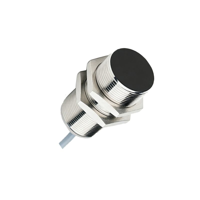
2. NPN (Sinking): The output switch connects the load to ground (0V). When activated, it "sinks" current from the load.
3. Analog Output: Provides a continuously variable signal (e.g., 0-10V, 4-20mA) proportional to the distance to the target.
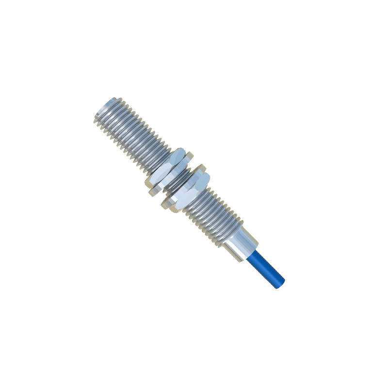
4. NAMUR (Intrinsically Safe): Used in hazardous areas; requires an associated barrier or isolator.
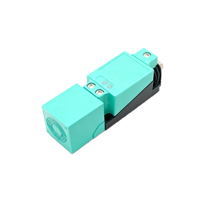
Always consult the sensor's datasheet. The part number and label on the housing will explicitly state the type (e.g., "INDUCTIVE PNP NO").
Standard Wiring Color Codes and Terminals
While colors can vary by manufacturer, IEC/EN 60947-5-2 defines a common standard:
Brown (BN): Connected to the positive DC supply voltage (+V, typically 10-30V DC).
Blue (BU): Connected to the negative DC supply voltage (0V, common).
Black (BK): The switched output signal wire (for 3-wire models).
White (WH): Often used for a second output or function (e.g., complementary output, timer function).
Shield: A bare or green/yellow wire for grounding the shield to reduce electromagnetic interference.
A 3-wire sensor has BN, BU, and BK wires. A 4-wire sensor may have two output wires (e.g., one Normally Open and one Normally Closed).
Step-by-Step Connection Procedure for 3-Wire DC Sensors
Follow this systematic procedure for a standard DC PNP or NPN sensor connection.
1. Safety First:
De-energize and lock out/tag out (LOTO) the control circuit.
Verify the voltage is off using a multimeter.
2. Prepare and Identify:
Review the sensor datasheet and the PLC/controller input module specifications.
Identify the power supply: a stable 24V DC is industry standard.
Determine if your controller input is sinking or sourcing. A PNP sensor pairs with a sinking input. An NPN sensor pairs with a sourcing input. Mismatching will not work.
3. Wiring a PNP Sensor (to a Sinking PLC Input):
Connect the Brown (BN) wire to the +24V DC terminal of the power supply.
Connect the Blue (BU) wire to the 0V (Common) terminal of the same power supply.
Connect the Black (BK) output wire to the input channel of your PLC (e.g., I0.0).
Connect the common terminal of that PLC input module to the 0V (Common) of the power supply. This completes the circuit. When the sensor detects an object, it switches the Black wire to +24V, sourcing current into the PLC input.
4. Wiring an NPN Sensor (to a Sourcing PLC Input):
Connect the Brown (BN) wire to +24V DC.
Connect the Blue (BU) wire to 0V.
Connect the Black (BK) output wire to the input channel of your PLC.
Connect the common terminal of that PLC input module to the +24V of the power supply. When activated, the NPN sensor switches the Black wire to 0V, sinking current from the PLC input to ground.
5. Connection of the Load (Alternative to PLC):
If driving a relay, lamp, or solenoid directly:
For a PNP sensor, place the load between the sensor's Black output wire and 0V.
For an NPN sensor, place