In the complex and electrically noisy environment of modern industrial automation, the reliable operation of sensors is paramount. Among these, proximity sensors play a critical role in non-contact detection, object positioning, and counting. However, electromagnetic interference (EMI), radio frequency interference (RFI), and crosstalk from adjacent machinery can cause false triggering, signal degradation, or complete sensor failure. This is where the principles of anti-interference proximity sensors become essential. This article delves into the core technologies and design methodologies that enable these sensors to maintain high accuracy and reliability amidst challenging conditions.
At its foundation, a proximity sensor detects the presence or absence of an object within a defined sensing range without physical contact. Common types include inductive (for metals), capacitive (for various materials including liquids), and photoelectric sensors. The vulnerability to interference is inherent because their operation relies on subtle changes in electromagnetic fields, capacitance, or light beams, which can be easily masked or mimicked by external noise.
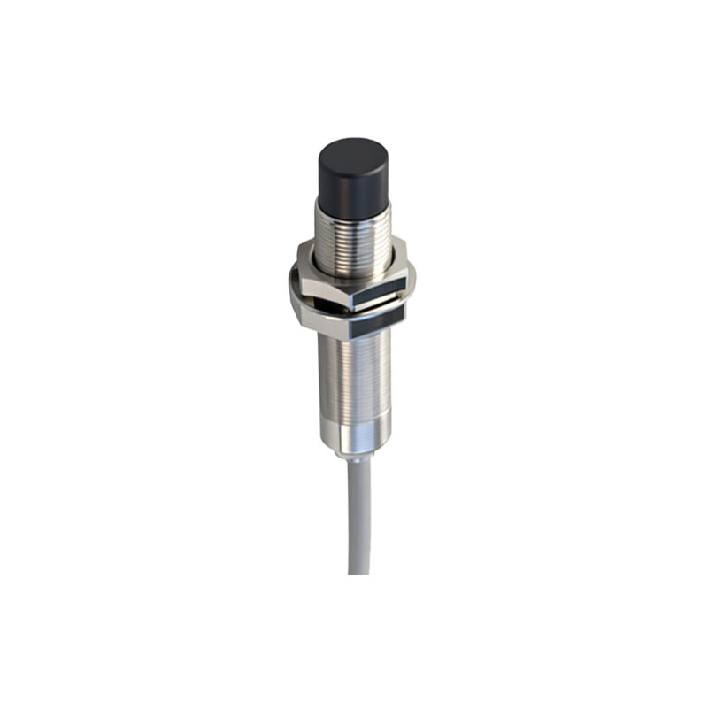
The first line of defense in anti-interference design is shielding. Metallic housings, typically made of brass, stainless steel, or nickel-plated brass, act as Faraday cages, attenuating external electric fields. For inductive sensors, a ferrite core is often incorporated to concentrate the sensor's own magnetic field while providing a degree of magnetic shielding. The shielding must be carefully designed to cover the sensor head completely, with particular attention to cable entry points, which are potential ingress points for noise.
Signal Modulation and Demodulation is a sophisticated and highly effective principle. Instead of emitting a simple, continuous wave or DC field, the sensor's oscillator generates a high-frequency, modulated signal (e.g., amplitude modulation or frequency modulation). The sensing circuit is then tuned to detect only this specific modulated pattern. Common industrial noise sources, which are often broadband or at different frequencies, are effectively filtered out because they do not match the expected modulation signature. This is analogous to tuning a radio to a specific station; other signals are rejected.
Advanced Filtering Circuits are integrated into the sensor's electronics. These include:
Band-pass filters: They allow only the sensor's operating frequency band to pass through, blocking both lower and higher frequency noise.
Digital filtering: In microcontroller-based sensors, algorithms like moving average filters or median filters process the digital signal over time, smoothing out short-duration noise spikes that could cause a false trigger.
Hysteresis: This is a fundamental software and hardware technique where the "ON" detection threshold is different from the "OFF" threshold. This creates a dead band that prevents the output from chattering rapidly when a target is at the edge of the sensing range or when noise causes minor signal fluctuations.
Synchronous Detection (for Photoelectric Sensors) is a key technique, especially in diffuse-reflective models susceptible to ambient light. The sensor's LED is pulsed at a specific high frequency. The receiver circuit is synchronized to look for light pulses only at that exact frequency and timing. Sunlight, workshop lighting (which often has a 50/60Hz flicker), or other stray light sources are ignored because they are not synchronized with the emitter's pulse pattern.
Physical and Electrical Design Considerations are equally crucial:
Cable Design: Using shielded, twisted-pair cables is standard. The twisting minimizes loop area, reducing inductive pickup of magnetic fields. The shield, properly grounded at one end (typically at the controller), drains away capacitive coupled noise.
Output Circuit Design: Solid-state outputs (PNP/NPN) with short-circuit protection, overload protection, and reverse polarity protection are more robust against electrical transients. Some sensors feature M12 or M8 connectors with integrated shielding.
Grounding and Installation: Proper system grounding is perhaps the most critical, yet often overlooked, aspect. Creating a single-point star ground for the control panel and ensuring low-impedance paths prevent ground loops, which are a major source of interference. Maintaining adequate physical separation between sensor cables and high-power AC lines is a fundamental installation rule.
Immunity Standards and Testing define the performance of these sensors. Key international standards include:
IEC 60947-5-2: Specifies requirements for proximity sensors, including dielectric (insulation) strength, operational behavior, and EMC (Electromagnetic Compatibility) immunity.
EMC Immunity Tests: Sensors are rigorously tested against:
Electrostatic Discharge (ESD): Simulating a human or object discharge.
Radiated RF Fields: Exposure to strong radio signals.
Fast Transient Bursts (EFT/B): Simulating noise from relays or contactors.
Surge Immunity: Simulating lightning strikes or major power system switches.