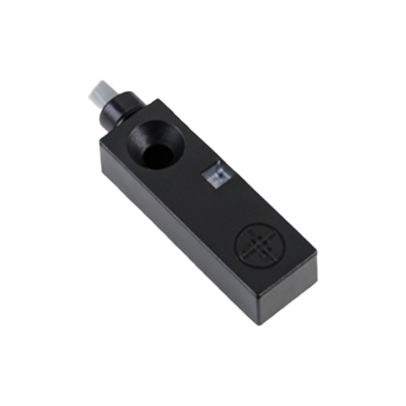
Proximity sensors are critical components in industrial automation, widely used for position detection, object counting, and safety systems in machinery. Proper wiring is essential to ensure reliable operation, especially in export applications where electrical standards and environmental conditions may vary. This guide provides a comprehensive overview of wiring techniques for common types of proximity sensors, including inductive, capacitive, and ultrasonic models, with a focus on international compliance and best practices.
First, identify the sensor type and its specifications. Inductive proximity sensors, typically used for metal detection, are available in two-wire, three-wire, and four-wire configurations. Three-wire sensors are most common in export markets, with wiring color codes often following international standards: brown for positive voltage (10-30V DC), blue for negative or ground, and black for the output signal. For AC-powered sensors, brown and blue wires usually connect to live and neutral lines, while black serves as the output. Always refer to the manufacturer’s datasheet, as colors may vary by region or brand.
For DC three-wire sensors, start by connecting the power supply. Ensure the voltage matches the sensor’s rating (e.g., 12V DC or 24V DC). Connect the brown wire to the positive terminal and the blue wire to the negative terminal. The black output wire links to the load, such as a PLC input, relay, or indicator. If the sensor is NPN (sinking output), the black wire provides a negative signal when activated; for PNP (sourcing output), it provides a positive signal. In export setups, verify local electrical norms—for instance, European systems often prefer PNP, while Asian markets may use NPN.
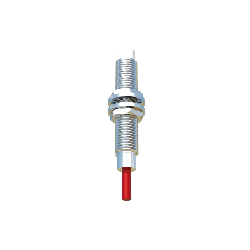
Two-wire sensors simplify wiring but require careful load matching. Connect one wire to the power source and the other to the load, ensuring the current draw stays within sensor limits. These sensors are suitable for basic applications but may have higher leakage currents, which can affect sensitive controllers. Four-wire sensors, with dual outputs (e.g., normally open and normally closed), offer flexibility for complex circuits. Wire the power lines first, then connect outputs as needed for fail-safe or logic operations.
Shielding and grounding are vital for noise immunity, especially in environments with motors or frequency drives. Use shielded cables, grounding the shield at the controller end only to prevent ground loops. Maintain short cable runs and avoid parallel routing with high-voltage lines. For export to areas with harsh conditions (e.g., high humidity or temperature extremes), choose sensors with appropriate IP ratings and use conduit or sealed connectors.
Testing and compliance are crucial. After wiring, power the system and check the sensor’s indicator LED. Use a multimeter to verify output voltage or current. Ensure the installation meets international standards like IEC 60947-5-2 for proximity devices and regional certifications (e.g., CE, UL, or CCC). Document wiring diagrams for maintenance, using clear labels and following color codes consistent with the destination country’s practices.
In summary, wiring proximity sensors for export requires attention to electrical standards, sensor type, and environmental factors. By adhering to manufacturer guidelines and international protocols, engineers can achieve robust, compliant installations that enhance automation system performance globally.