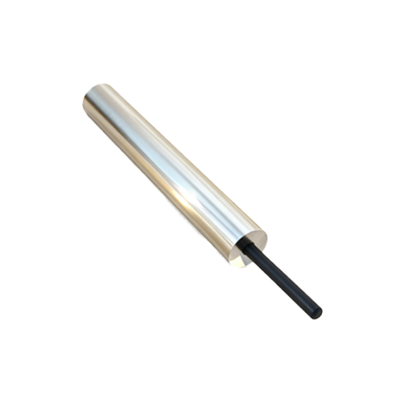
Proximity sensors are indispensable components in modern automation, robotics, and safety systems. They detect the presence or absence of an object without physical contact, using various principles such as electromagnetic, capacitive, or optical methods. For engineers and hobbyists looking to understand the underlying technology or create a custom solution, building a basic inductive proximity sensor from scratch offers valuable insights. This guide outlines a fundamental approach to constructing a simple, functional inductive proximity sensor, commonly used for detecting metallic objects.
The core principle of an inductive proximity sensor involves generating an electromagnetic field via a coil. When a metallic object enters this field, eddy currents are induced in the object, which in turn alter the oscillation characteristics of the sensor's LC (inductor-capacitor) tank circuit. This change can be detected and converted into a usable output signal. The primary components required include a copper wire coil (air-core or ferrite-core), capacitors to form the resonant circuit, an oscillator circuit (often using a transistor or an IC like the 555 timer), a detection circuit (such as a peak detector or comparator), and a power supply (typically 5V to 24V DC). Optional components for output stages include a relay, an LED indicator, or an open-collector transistor.
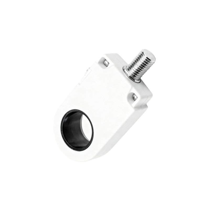
Begin by designing the sensing coil. The coil's inductance is critical; it determines the operating frequency and sensing range. For a simple sensor, wind approximately 50-100 turns of enameled copper wire (around 0.2-0.5 mm diameter) onto a ferrite rod or in a flat spiral pattern. Measure the inductance using an LCR meter; a typical target range is between 1 mH to 10 mH. Next, build the oscillator circuit. A Colpitts or Hartley oscillator using a bipolar junction transistor (BJT) like the BC547 is a common choice. Connect the coil in parallel with a capacitor (e.g., a 1 nF to 100 nF ceramic capacitor) to create the LC tank. The capacitor value should be chosen to resonate with the coil at a frequency typically between 100 kHz to 1 MHz. The formula f = 1 / (2π√(LC)) guides this selection. The oscillator generates a continuous high-frequency signal when no target is present.
The detection circuit monitors the oscillator's amplitude. When a metal object approaches the coil, energy loss due to eddy currents causes the oscillation amplitude to drop. This amplitude change can be captured using a diode (e.g., 1N4148) and a capacitor to create a simple envelope detector (peak detector). The resulting DC voltage level will decrease as the target nears. Feed this DC signal into a comparator IC, such as an LM393. Set a reference voltage on the comparator's inverting input using a voltage divider (potentiometers are useful for adjusting sensitivity). When the detected voltage falls below the reference, the comparator's output switches state (e.g., from high to low), indicating detection.
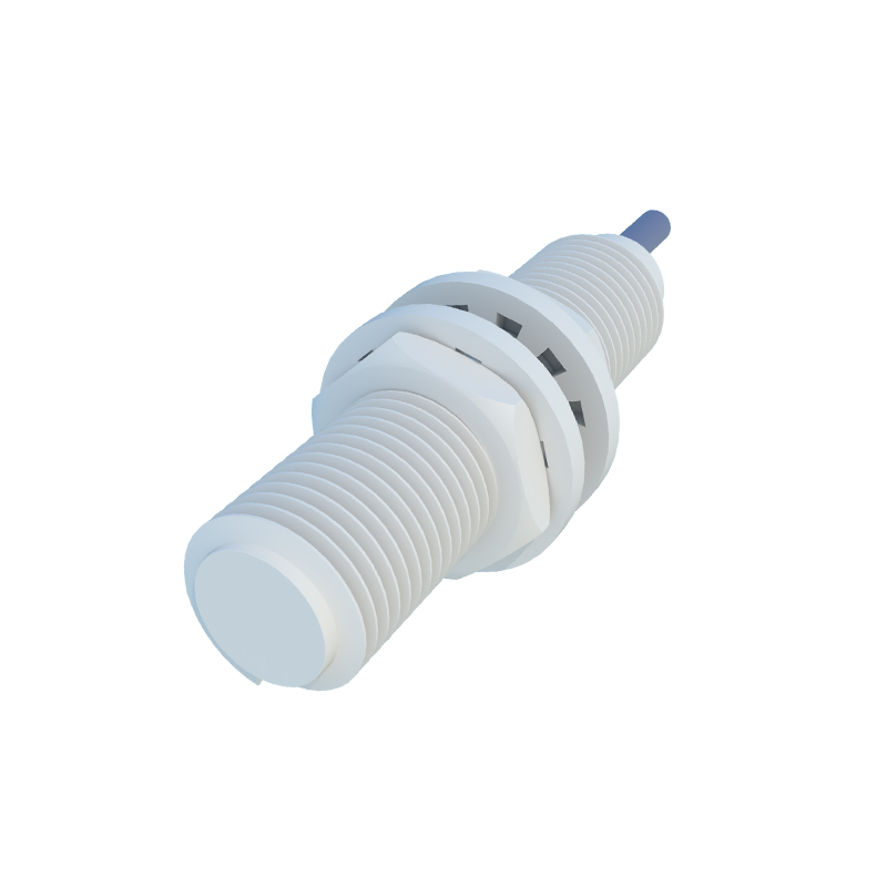
Finally, implement the output stage. The comparator's output can drive a small LED directly (with a current-limiting resistor) for visual indication. For switching higher loads, connect the output to the base of a transistor (like a 2N2222) configured as a switch, which can then control a relay or provide an open-collector NPN output standard in industrial sensors. Ensure proper power supply decoupling with bypass capacitors (e.g., 100 nF ceramic) near the ICs to prevent noise interference. Enclose the entire circuit in a suitable non-metallic housing, with only the sensing coil exposed. Calibration is essential: adjust the potentiometer for the reference voltage so that the output triggers reliably at the desired sensing distance, which for a homemade sensor might be a few millimeters.
While this basic design demonstrates the fundamental working principle, commercial proximity sensors incorporate advanced features like temperature compensation, noise immunity, and various output formats (PNP/NPN, analog, IO-Link). Building this circuit provides hands-on understanding of electromagnetic sensing, oscillator stability, and signal conditioning. It's an excellent educational project that bridges theoretical knowledge with practical electronics, emphasizing the importance of component selection, PCB layout for noise reduction, and precise calibration for reliable operation in real-world environments.