In industrial automation and control systems, proximity sensors are indispensable components for non-contact detection of metallic or, in some cases, non-metallic objects. Their reliability is paramount for ensuring smooth production flow, machine safety, and process consistency. However, signal anomalies from these sensors are a frequent source of downtime and troubleshooting headaches for maintenance engineers and technicians. Understanding the root causes, diagnostic procedures, and corrective actions is essential for maintaining operational efficiency.
Signal anomalies typically manifest in several ways: intermittent operation (fluttering), complete failure to detect, false triggering, or an unstable output signal. These issues can stem from a wide array of factors, often categorized into environmental, electrical, mechanical, and sensor-specific causes.
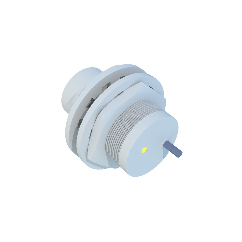
A primary suspect is environmental interference. Proximity sensors, especially inductive types, operate by generating an electromagnetic field. The presence of strong external magnetic fields, such as those from large motors, transformers, or welding equipment, can distort this field, leading to false signals or reduced sensing range. Similarly, conductive contaminants like metal chips, dust, or filings can accumulate on the sensor face, effectively "shielding" the target or altering the field characteristics. For capacitive sensors, variations in humidity, temperature, or the presence of non-target materials (like dust or fluids) can change the dielectric constant, causing erratic behavior. Ensuring proper sensor selection for the environment—choosing units with appropriate IP ratings, temperature tolerances, and immunity ratings—is the first line of defense.
Electrical issues constitute another major category. Voltage fluctuations or instability in the DC power supply can directly impact sensor performance. Sensors operating near their minimum or maximum voltage limits may become unreliable. Electrical noise, often from Variable Frequency Drives (VFDs), solenoids, or communication cables run in parallel, can be induced into the sensor or its signal lines. This noise can be misinterpreted by the controller as a valid switching signal. Implementing noise suppression strategies is critical: using shielded cables with the shield properly grounded at the controller end (not at the sensor), installing ferrite cores on cables near noise sources, and ensuring proper separation between power and signal lines are standard practices. Additionally, checking for proper wiring—secure connections, correct polarity, and undamaged cables—is a fundamental but often overlooked step.
Mechanical factors are frequently the culprit. Incorrect installation is common. The sensor must be mounted securely to prevent vibration from altering the gap between the sensor and the target. The sensing distance must respect the sensor's rated operating distance, typically 70-80% of its nominal range to account for target material variations and temperature drift. Misalignment, where the target does not approach the sensor face directly and perpendicularly, can drastically reduce effective range. Wear and tear on the sensor body or face from physical impact or abrasive materials can also degrade performance. Regular inspection of the mounting hardware, alignment, and sensor physical condition is necessary.
Finally, the sensor itself or its interaction with the target may be the issue. All proximity sensors have a specified sensing range for different materials. Using a standard inductive sensor to detect stainless steel, for example, will result in a significantly reduced range compared to mild steel. Selecting a sensor specifically designed for the target material (e.g., factor-1 for mild steel, factor-0.7 for stainless) is crucial. Sensor aging, though gradual, can occur. Internal oscillator components may drift, or output transistors may weaken over time, leading to a gradual reduction in performance. In such cases, replacement is the only solution.
A systematic diagnostic approach is recommended. Start with the simplest checks: visually inspect for physical damage, contamination, and secure mounting. Verify the power supply voltage at the sensor terminals under load. Use an oscilloscope to observe the output signal for noise or instability, which is far more revealing than a multimeter's DC voltage reading. Temporarily substitute the sensor with a known-good unit from a similar application (if safe and possible) to isolate the problem to the sensor or the external circuit. Monitor the system's behavior while gently manipulating cables and connections to identify intermittent faults.
In conclusion, proximity sensor signal anomalies are rarely mysterious. They are logical failures with identifiable causes. A methodical troubleshooting process that considers environmental conditions, electrical integrity, mechanical setup, and sensor specifications will quickly isolate most problems. Proactive maintenance, including regular cleaning, electrical checks, and adherence to installation guidelines, significantly reduces the occurrence of these disruptive faults, ensuring robust and reliable automation system performance.