In modern industrial environments, electrical and magnetic interference is a pervasive challenge. Laser sensors, prized for their precision in distance measurement, object detection, and positioning, must often operate reliably amidst strong electromagnetic fields generated by motors, transformers, and power lines. This article explores the principles behind magnetic field immunity in laser sensors and the engineering approaches that ensure their stable performance.
The core of a laser sensor's operation involves emitting a laser beam and analyzing the reflected light. The critical components susceptible to magnetic influence are typically not the optical elements themselves but the supporting electronics: the photodetector circuitry, signal amplifiers, and communication interfaces. Strong magnetic fields can induce unwanted currents in these circuits, leading to signal noise, measurement drift, or complete operational failure.
Achieving magnetic field immunity is a multi-faceted design task. First, component selection is paramount. Using magnetically insensitive materials for critical parts and opting for integrated circuits with high common-mode rejection ratios (CMRR) forms the first line of defense. Second, shielding is a classical and effective method. Enclosing sensitive electronic modules in housings made from high-permeability alloys, such as mu-metal, creates a path that redirects and contains magnetic flux, preventing it from penetrating the internal circuitry.
Furthermore, circuit design plays a crucial role. Differential signaling techniques, where the measurement signal is transmitted as the difference between two complementary voltages, are highly effective at rejecting magnetically induced common-mode noise. Proper board layout, with careful grounding schemes and the strategic placement of components to minimize loop areas that can act as antennas for interference, is equally critical. Advanced digital signal processing (DSP) algorithms can then filter out any residual noise that penetrates the physical and circuit-level defenses.
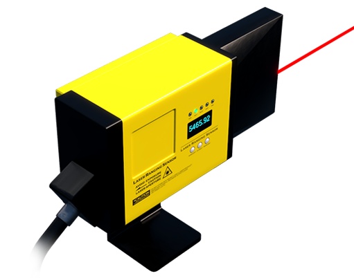
For applications in extreme environments, such as near MRI machines or large industrial magnetizers, manufacturers often subject laser sensors to standardized testing. Compliance with standards like IEC 61000-4-8, which defines immunity test levels for power frequency magnetic fields, provides a quantifiable benchmark. A sensor rated for 100 A/m or higher, for instance, is suitable for most harsh industrial settings.

In practice, selecting a laser sensor with declared magnetic field immunity specifications is essential for system integrators. Key parameters to review in datasheets include the tested field strength (in A/m or Gauss), the frequency range of immunity (e.g., 50/60 Hz for power lines, or broader ranges for variable-frequency drives), and any resultant degradation in measurement accuracy under such conditions. Field tests in the actual installation environment remain the gold standard for validation.
Ultimately, the magnetic field immunity of a laser sensor is not an accidental feature but the result of deliberate design choices at the material, component, circuit, and software levels. As industries increasingly automate and deploy sensitive equipment in electromagnetically congested areas, this characteristic transitions from a desirable advantage to a fundamental requirement for ensuring continuous, accurate, and safe operations. Engineers must prioritize this specification to build robust systems capable of withstanding the invisible yet potent challenges posed by magnetic interference.