In the realm of industrial automation and electrical engineering, proximity sensors play a crucial role in detecting the presence or absence of objects without physical contact. Their representation in electrical schematics and circuit diagrams is standardized through specific symbols, which are essential for engineers and technicians to interpret designs accurately. This article delves into the common symbols used for proximity sensors, their variations, and practical insights for reading and applying them in real-world projects.
Proximity sensors are broadly categorized based on their sensing technology: inductive, capacitive, ultrasonic, and photoelectric. Each type has a distinct symbol that conveys its function and electrical characteristics. The International Electrotechnical Commission (IEC) and the Institute of Electrical and Electronics Engineers (IEEE) provide guidelines for these symbols, though variations may exist depending on regional standards or company-specific drafting practices.
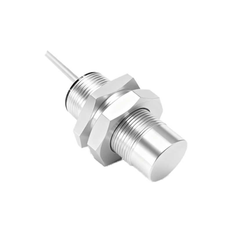
The most common symbol for an inductive proximity sensor, used to detect metallic objects, resembles a coil or inductor with a diamond shape attached. The diamond often includes a vertical line, indicating the sensing face or active area. In schematics, this symbol is typically labeled with "PR" or "PROX" and may include additional notations for output type (e.g., NPN or PNP) and connection points. For example, a three-wire inductive sensor symbol shows two lines for power supply (usually +V and GND) and one for the output signal. The output line might be depicted with a switch-like icon to represent its switching function—normally open (NO) or normally closed (NC).
Capacitive proximity sensors, capable of detecting both metallic and non-metallic materials, share a similar diamond-shaped symbol but often include a parallel plate design within the diamond to signify capacitance. This subtle difference helps engineers quickly identify the sensor type in a crowded diagram. The labeling might include "C" or "CAP" to avoid confusion.
Photoelectric sensors, which use light beams for detection, are represented by a symbol combining a light source (often a diode shape) and a receiver, enclosed in a diamond or rectangle. Arrows indicate the direction of light emission and reception, with variations for through-beam, retro-reflective, and diffuse reflective modes. For instance, a through-beam sensor shows two separate symbols for transmitter and receiver, while a diffuse reflective version integrates both into a single symbol with a reflected arrow.
Ultrasonic sensors, employing sound waves, feature a symbol with wave-like lines emanating from a diamond or circle, sometimes resembling a loudspeaker icon. This visual cue emphasizes the use of acoustic signals for distance measurement or object detection.
When interpreting these symbols in electrical schematics, it is vital to refer to the accompanying legend or bill of materials. Symbols alone may not specify details like sensing range, voltage ratings, or housing styles. Engineers should also note the numbering or tagging system—such as "PS1" for Proximity Sensor 1—which links the symbol to specifications in documentation. In ladder logic diagrams, proximity sensors are often shown as input contacts, with their symbols integrated into control circuits to illustrate logic sequences.
Practical application requires understanding how these symbols translate to wiring and installation. For example, a symbol with a shielded ground line indicates a sensor designed for environments with electromagnetic interference. Similarly, symbols with dashed lines might represent adjustable sensing parameters or diagnostic features. Always cross-check with manufacturer datasheets, as proprietary symbols can differ; a sensor from Brand X might use a filled diamond, while Brand Y uses an outline.
In summary, proximity sensor symbols serve as a universal language in electrical engineering, bridging design and implementation. Mastery of these symbols enhances efficiency in troubleshooting, system integration, and compliance with safety standards. As technology evolves, new symbols may emerge for smart sensors with IO-Link or wireless capabilities, but the core principles of clarity and standardization remain. By familiarizing oneself with these graphical representations, professionals can ensure accurate communication and robust automation solutions.