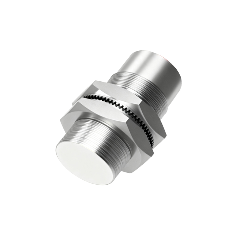
Proximity sensors, often referred to as proximity switches or non-contact sensors, are fundamental components in modern industrial automation, robotics, and safety systems. A proximity sensor circuit is the complete electronic system that enables the detection of an object's presence or absence within a specific range without any physical contact. This article delves into the core principles, common types, and key design considerations for these essential circuits.
At its heart, a proximity sensor circuit operates by generating an electromagnetic field or a beam of radiation (like infrared light) and detecting changes in that field or the return signal. The primary components of a typical circuit include an oscillator, a sensing coil or emitter (for generating the field), a detection circuit (for sensing changes), a signal amplifier, and an output stage (like a solid-state switch or an analog voltage output). The oscillator creates a high-frequency electromagnetic field at the sensing face. When a metallic or other target object enters this field, it induces eddy currents, which in turn cause a change in the oscillation amplitude or frequency. The detection circuit senses this change, and the signal is processed and amplified to trigger the output.
Several technologies dominate the landscape of proximity sensing circuits. Inductive proximity sensors are the most common for detecting metallic objects. Their circuits are tuned to sense the eddy current losses caused by ferrous and non-ferrous metals. Capacitive proximity sensor circuits, on the other hand, can detect both metallic and non-metallic materials (like plastic, wood, or liquids) by sensing changes in capacitance when an object alters the electrostatic field around the sensor's face. Photoelectric proximity sensors use an LED or laser emitter and a phototransistor or photodiode receiver in their circuit. The detection logic can be through-beam (object breaks the beam), retro-reflective, or diffuse (reflective). Ultrasonic proximity sensor circuits employ a transducer to emit and receive high-frequency sound waves, measuring the time-of-flight to determine distance, making them excellent for level detection and harsh environments.
Designing a robust proximity sensor circuit requires careful attention to several factors. First is the sensing range, which is specified as the nominal range (Sn) under standardized conditions. Real-world mounting (flush or non-flush), target material, size, and shape significantly affect the actual sensing distance. The circuit must be designed to compensate for or be immune to these variations. Electrical characteristics are paramount: operating voltage (commonly 10-30V DC or 90-250V AC), output type (NPN/PNP sinking/sourcing, NO/NC), and current rating. Protection features like short-circuit protection, reverse polarity protection, and overload protection are integral to industrial-grade circuits. Environmental robustness is another critical consideration. Circuits must be designed to withstand temperature extremes, humidity, vibration, and exposure to chemicals or washdowns. Electromagnetic compatibility (EMC) is a major design challenge; the circuit must not emit excessive interference and must be immune to noise from variable frequency drives, motors, and other industrial equipment. This often involves careful PCB layout, shielding, and the use of filters and ferrite beads.
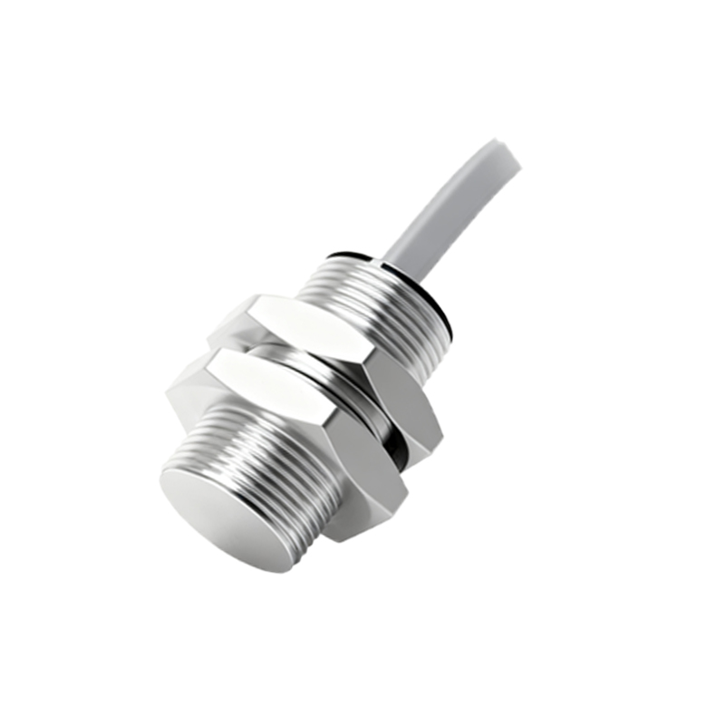
The output stage is a crucial part of the circuit. Many industrial proximity sensors provide a solid-state transistor output (either NPN or PNP configuration) for fast switching and long life, devoid of mechanical contacts found in traditional limit switches. Some circuits offer analog outputs (0-10V or 4-20mA) proportional to distance, enabling continuous position monitoring. Advanced circuits incorporate diagnostic features like IO-Link communication, which allows for parameter setting, condition monitoring, and detailed diagnostic data transmission back to the controller.
In application, these circuits are the backbone of countless automated processes. They are used for precise object detection on conveyor lines, part positioning in CNC machines, rotary speed sensing, coil windings count, and as safety devices in automated guarding systems. The choice of circuit technology—inductive, capacitive, photoelectric, or ultrasonic—depends entirely on the target material, required sensing distance, environmental conditions, and cost constraints.
Troubleshooting proximity sensor circuits typically involves checking power supply integrity, verifying the output load (ensuring it does not exceed the sensor's rating), inspecting for physical damage or contamination on the sensing face, and using an oscilloscope to examine the oscillator signal for abnormalities. Understanding the underlying circuit principles empowers engineers to select the right sensor, integrate it correctly into a control system (like a PLC), and diagnose issues efficiently, ensuring maximum uptime and reliability in automated systems.